

How To Install LED Strip TV Back Light?
Views: 0 Author: Site Editor Publish Time: 2026-07-10 Origin: Site


Installing a back light behind your television or monitor fundamentally transforms the viewing experience by introducing ambient bias lighting. This technique reduces visual fatigue and significantly increases the perceived contrast ratio of digital displays. When you stare at a bright screen in a dark room, your pupils constantly dilate and constrict. Bias lighting creates a neutral reference point, stabilizing pupil reaction and making on-screen blacks appear deeper.
Improper installation routinely results in uneven light dispersion, premature adhesive failure due to thermal stress, and inaccurate color rendering. These issues degrade the viewing or inspection experience. Many users rush the process, failing to clean the mounting surface or bending the delicate circuitry too sharply. This leads to broken traces and dead diodes.
We will explore a systematic, engineering-based approach to selecting, preparing, testing, and installing LED strips. Following these steps ensures long-term reliability, optimal optical performance, and safe power management for any display setup.
Pre-Installation Testing is Mandatory: Always unroll and fully power-test LED strips prior to adhesion to identify defective diodes or connection faults early.
Surface Preparation Dictates Lifespan: Adhesion longevity depends entirely on removing plasticizers and dust from the display chassis using proper solvents (e.g., 90% isopropyl alcohol).
Corner Routing Prevents Circuit Failure: Hard 90-degree bends fracture the flexible PCB traces; utilizing loop folds or dedicated corner connectors is mandatory for continuous operation.
Power Source Limitations: Relying on standard TV USB 2.0 ports (500mA limit) restricts brightness and stability; dedicated AC adapters or USB 3.0 ports are required for high-density strips.
Application Specificity: While consumer RGB/smart strips suffice for home entertainment, professional and industrial inspection environments require specialized solutions like a high-precision machine vision light.
Success Criteria for Display Backlighting
Optical Uniformity and Bias Lighting Standards
A proper lighting setup serves a specific physiological role. It reduces iris fatigue in dark environments by providing a smooth gradient of light behind the screen. This gradient prevents the sharp contrast between a bright monitor and a pitch-black wall. Your eyes remain relaxed during extended viewing sessions. When the ambient light behind the screen matches the average brightness of the display, the human eye perceives the contrast of the screen to be much higher. The black levels look inkier, and the highlights do not pierce the retina.
To achieve accurate color perception, you must establish baseline optical targets. The industry standard for true white bias lighting is a 6500K color temperature, known as the D65 standard. This specific temperature matches the white point calibration of broadcast monitors and consumer televisions. Additionally, the light source should possess a Color Rendering Index (CRI) of greater than 90. Lower CRI values cast unnatural color tints that distort the on-screen image. If you use a cheap LED strip with a CRI of 70, the light bouncing off your wall will likely have a green or magenta shift, ruining the color accuracy of the content you are watching.
You must maintain a specific offset distance from the wall to achieve a diffuse, uniform halo. Mounting the display too close to the wall creates harsh, distinct light points. A distance of two to six inches generally allows the individual diodes to blend into a seamless wash of light. If your television is mounted on an ultra-slim wall bracket, you might need to use a high-density LED strip (such as 120 LEDs per meter) to eliminate the "spotlight" effect and achieve a smooth glow.
Power and Thermal Management
Evaluating power draw requirements is critical for system stability. Standard 5V USB setups offer convenience since they plug directly into the display. However, they often lack the amperage required for high-density strips. A standard USB 2.0 port outputs a maximum of 500mA. If you connect a three-meter strip of SMD 5050 LEDs to this port, the television's power board will either shut down the port to protect itself, or the LEDs will flicker and dim significantly. Dedicated 12V or 24V power supplies provide consistent voltage over longer runs, eliminating dimming issues.
You must analyze the thermal output of the display panel. Modern televisions generate significant heat, especially near the internal power supply and the main processing board. This heat transfers directly to the LED strip's operating temperature. Excessive thermal loads degrade the adhesive backing and shorten the lifespan of the diodes. Proper placement avoids the hottest zones on the rear chassis. When planning your routing path, use an infrared thermometer to map the back of the television after it has been running for an hour. Keep the LED strips at least two inches away from any surface exceeding 40 degrees Celsius.
Smart Ecosystem and Synchronization Standards
Modern lighting systems often integrate with smart home protocols. Thread, Matter, Wi-Fi, and Zigbee dominate the landscape. Premium systems utilize these protocols for seamless voice control and automation. Choosing a compatible protocol ensures the lighting responds instantly to commands without network congestion. Zigbee systems require a dedicated hub but offer exceptional reliability and low latency. Wi-Fi strips connect directly to your router but can crowd your network if you have dozens of smart devices.
You must understand the technical difference between static lighting and dynamic synchronization. Static bias lighting provides a constant white glow, which is optimal for critical viewing and color accuracy. Camera-based screen-sync systems capture the screen image using a small camera mounted on the TV bezel and adjust the LEDs accordingly. These systems introduce slight processing latency and sometimes struggle with letterboxed movies. Direct HDMI sync boxes intercept the video signal for zero-latency color accuracy, offering the most immersive experience, though they cannot process signals from built-in smart TV apps.
Pre-Installation: Evaluating and Selecting Your Back Light
Consumer LED Strips vs. Smart Entertainment Systems
Consumer options fall into three distinct categories. Static white strips offer simple, effective bias lighting. They usually feature a single inline switch and provide the most accurate D65 white light. Standard RGB or RGBW strips provide basic color changing capabilities via a remote. Addressable, IC-controlled strips allow individual segments to display different colors simultaneously, enabling dynamic, screen-synced effects. Addressable strips require more complex controllers and higher power draws.
Evaluate the trade-offs of smart controllers versus standard inline remotes. IR and RF remotes offer simplicity but require line-of-sight or suffer from limited range. Smart controllers provide extensive customization via mobile apps. However, they rely on your local network, which can introduce latency or potential security vulnerabilities if not properly configured. If you choose a smart controller, ensure it supports local network control so your lighting continues to function even if your internet connection drops.
Industrial Display and Inspection Alternatives
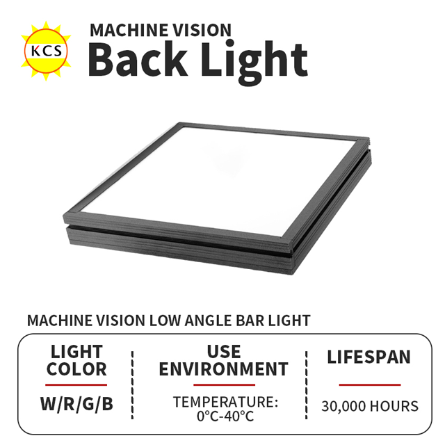
Consumer TV backlights differ vastly from a dedicated machine vision light. Professional QA, automated sorting, and testing environments demand absolute uniformity and precision. These industrial tools prioritize optical consistency over dynamic color changes. They use tightly binned LEDs to ensure every unit outputs the exact same wavelength of light, which is necessary for machine learning algorithms to accurately identify defects on an assembly line.
Specific scenarios require an Industrial Machine Vision LED Backlight Source behind a display or inspection stage. High-contrast defect detection relies on silhouetting the target object. Ambient bias lighting cannot provide the intense, focused illumination necessary for automated cameras to detect microscopic flaws. These industrial sources are built with heavy-duty aluminum housings that act as massive heat sinks, allowing the LEDs to be overdriven for short bursts of intense light synchronized with a camera shutter.
Mechanical integration often dictates the equipment choice. A Customizable Hole Machine Vision Backlight Source accommodates specialized setups. This design allows a camera lens to pass directly through the center of the illumination plane. It eliminates shadows and provides perfectly coaxial lighting for complex inspection tasks. You will find these units in electronics manufacturing, where cameras must inspect solder joints on printed circuit boards without any cast shadows obscuring the view.
Energy efficiency and thermal output are paramount in continuous-duty environments. Specifying a Low Power LED Backlight for Vision Inspection ensures stable operation for control room monitors. These units manage heat effectively, preventing thermal degradation during 24/7 duty cycles. In a factory running three shifts, the lighting cannot fail or shift in color temperature over time, as this would require recalibrating the entire vision system.
Feature | Consumer LED Strips | Industrial Machine Vision Lighting |
|---|---|---|
Primary Use Case | Home entertainment, ambient bias lighting | Automated inspection, defect detection |
Color Accuracy | Variable (often prioritized for saturation) | Strictly calibrated (high CRI, exact wavelengths) |
Power Supply | 5V USB or standard 12V adapters | Regulated 24V industrial power supplies |
Thermal Management | Basic passive cooling via FPCB | Advanced heat sinks for continuous duty |
Mounting Method | Double-sided adhesive tape | Rigid aluminum brackets and M4/M6 bolts |
Step-by-Step Installation Framework
Phase 1: Unboxing, Inspection, and Dry Testing
Start with the unrolling protocol. Carefully unroll the entire strip onto a clean, non-conductive surface. Never apply power while the strip remains spooled on the plastic reel. The concentrated heat will melt the backing and destroy the diodes within minutes. The flexible printed circuit board acts as a minor heat sink when unrolled, but when coiled, the heat has nowhere to escape.
Perform a functional diagnostic test immediately. Connect the strip to its controller and power source. Cycle through primary colors and pure white. Verify uniform color rendering and brightness across the entire length. Check remote or app responsiveness before mounting anything to the display. Look closely at the last few inches of the strip. If the white light looks yellow or red at the end, the strip is suffering from voltage drop, and you will need a higher-rated power supply or a shorter run.
Phase 2: Surface Preparation and Measurement
Execute a strict cleaning protocol. First, disconnect the display power completely. Use a clean microfiber cloth and 90% or higher isopropyl alcohol. Vigorously wipe the rear plastic housing. You must strip away manufacturing oils, plasticizers, and household dust. Failure to do this guarantees the adhesive will fail. Do not use household glass cleaners or multi-surface sprays, as they leave behind a thin film of residue that prevents the acrylic adhesive from bonding to the plastic.
Apply the measurement formula to determine the optimal path. Calculate the perimeter of the rear chassis. Establish a two-to-three-inch offset from the outer edge. This specific placement hides the diodes from direct view while maximizing the light diffusion against the wall behind the screen. Use small pieces of masking tape to mark the corners of your planned route. This gives you a visual guide to follow once you start peeling the adhesive backing.
Phase 3: Sizing, Cutting, and Corner Management
Identify the correct sizing and cut marks. Look for exposed copper pads featuring small scissor icons. You can safely sever the Flexible Printed Circuit Board (FPCB) at these exact points. Cutting anywhere else breaks the serial circuit, rendering the remaining segment useless. Use sharp scissors to make a clean, straight cut directly through the center of the copper pads, leaving enough copper on both sides if you plan to use solderless connectors.
Understand corner navigation mechanics to prevent damage. The FPCB has strict mechanical limits. Hard creases cause trace delamination, severing the electrical connection. You must use specific techniques to navigate 90-degree turns safely. If you break a trace, the rest of the strip downstream will lose power or lose specific color channels.
Measure the exact distance to the corner and mark the strip.
Choose your corner method: The Loop Method involves gently curving the strip outward, creating a small loop at the corner without creasing the copper traces.
Alternatively, use the Accordion Fold: Carefully fold the strip back on itself at a 45-degree angle, pinching only the very edge to change direction. Do not press down hard on the fold.
For the most secure installation, cut the strip at the designated pads and use L-shaped ribbon connectors. Slide the copper pads under the metal pins of the connector and snap the plastic clip shut.
Phase 4: Adhesion, Thermal Bonding, and Power Connection
Utilize a progressive adhesion technique. Peel back only six inches of the protective liner at a time. Press the strip firmly onto the cleaned surface, smoothing it as you go. This method prevents trapping air bubbles and ensures maximum contact area for the thermal adhesive. Apply firm pressure with your thumb for at least five seconds on each section to activate the pressure-sensitive adhesive.
Identify high-heat zones on the TV chassis. These areas typically reside near the internal power supply or main processor. The heat will eventually soften the standard adhesive. Apply supplemental high-temperature adhesive clips in these zones to provide mechanical support. Space these clips every twelve inches along the top edge of the television, as gravity and heat will work together to pull the strip down over time.
Complete the final power-on sequence. Plug the strip into the designated power source. If using a USB port, verify it supplies adequate amperage. Secure any dangling controller cables or excess wire with zip ties and adhesive cable tie mounts. Loose cables add unnecessary weight that pulls on the adhesive over time. Route the power cable down the back of the TV stand or wall mount to keep the installation looking clean and professional.
Implementation Risks and Mitigation Strategies
Voltage Drop and Dimming
Voltage drop occurs frequently in 5V strips longer than three meters. You will notice the symptoms clearly. The light shifts toward red, or the brightness dims significantly at the far end of the strip. The thin copper traces simply cannot carry sufficient current over long distances. The resistance in the copper turns the electrical energy into heat, leaving less voltage for the LEDs at the end of the line.
Implement mitigation tactics to resolve this issue. Power injection at both ends of the strip balances the voltage distribution. This involves running a parallel wire from the power supply directly to the end of the strip. For larger displays exceeding 75 inches, upgrading to a 12V or 24V system is highly recommended. Higher voltage systems maintain consistent brightness across extensive lengths because they require less current to deliver the same amount of power, thereby reducing the resistance losses in the traces.
Signal Interference and Connectivity Failures
Infrared and radio frequency interference can disrupt operation. The television's native remote might inadvertently trigger the LED controller receiver. This causes random color changes or power cycling. You must isolate the control signals to ensure stable performance. Sometimes, the IR frequency of a soundbar volume control overlaps with the color-changing frequency of a cheap LED controller.
Advise on optimal placement of the controller dongle. For IR systems, ensure the receiver has a clear line-of-sight to your seating position. Tape the small IR receiver bulb to the bottom edge of the TV bezel. For Wi-Fi or Zigbee controllers, place the antenna in an unshielded location. Avoid tucking the controller behind heavy metal brackets that block wireless signals. If your router is in another room, ensure the 2.4GHz Wi-Fi signal is strong enough behind the television to maintain a stable connection.
Adhesive Failure and Sagging
Long-term adhesive degradation remains a primary concern. The constant thermal expansion and contraction of the TV chassis stress the mounting tape. Over months of use, the adhesive dries out, causing the strip to sag or detach completely. The plastic chassis of the television expands when hot and shrinks when cold, constantly pulling at the adhesive bond.
Recommend secondary mechanical support options to guarantee longevity. Install plastic mounting clips every two feet along the run. Use silicone-based double-sided mounting tape for areas that refuse to stick. Brackets provide absolute security for high-heat areas where chemical adhesives routinely fail. If you are mounting the strip to a heavily textured plastic surface, you may need to use an adhesion promoter sponge before applying the strip.
Failure Symptom | Root Cause | Mitigation Strategy |
|---|---|---|
End of strip looks red/dim | Voltage drop across the FPCB | Inject power at both ends or upgrade to 12V/24V |
Strip falls off after one week | Surface contamination or thermal stress | Clean with 90% IPA; add mechanical support clips |
Random color changes | IR interference from TV remote | Relocate IR receiver or upgrade to Wi-Fi/Zigbee control |
Dead section in the middle | Fractured copper trace from hard bending | Cut out damaged section and splice with connectors |
Conclusion
Measure the exact perimeter of your display's rear chassis to purchase the correct length of lighting.
Verify the amperage output of your intended power source to ensure it meets the requirements of your selected LED density.
Clean the mounting surface thoroughly with 90% isopropyl alcohol and allow it to dry completely before applying any adhesive.
Test the entire lighting system on the floor before removing the adhesive backing to catch any manufacturing defects early.
FAQ
Q: What is the optimal color temperature for a TV back light?
A: The optimal color temperature is 6500K, known as the D65 standard. This pure white light matches the color calibration of most digital displays. It provides a neutral reference point, ensuring accurate color perception without casting warm or cool tints on the surrounding walls.
Q: Why is it critical to test LED light strips before sticking them to the TV?
A: Testing unrolled strips verifies functionality before installation. It allows you to identify dead diodes, color inconsistencies, or faulty controllers. Discovering a defect after applying the adhesive makes returns difficult and wastes the time spent cleaning and routing the strip.
Q: Can I cut LED light strips anywhere, or are there specific cut points?
A: You must only cut the strips at designated cut points. These are marked by exposed copper pads, often accompanied by a small scissor icon. Cutting anywhere else severs the electrical circuit, causing the remaining section of the strip to fail permanently.
Q: Why do my TV LED strip lights keep falling off, and how do I prevent it?
A: Strips fall off due to poor surface preparation or thermal stress. Dust and plasticizers on the TV chassis prevent proper adhesion. Prevent this by cleaning the surface thoroughly with 90% isopropyl alcohol. Use mechanical support clips in high-heat areas near the TV's power supply.
Q: How do you power an LED back light without overloading the TV USB port?
A: Check the TV's USB port rating; most supply only 500mA (USB 2.0). High-density strips require more current. To avoid overloading the port, use a dedicated external AC adapter or plug the strip into a USB 3.0 port, which typically provides up to 900mA.
Q: What is the difference between a consumer TV backlight and an industrial machine vision light?
A: Consumer backlights prioritize dynamic colors and smart home integration for entertainment. Industrial lighting focuses on absolute optical uniformity, strict color calibration, and continuous-duty thermal management. Industrial units are used for high-contrast defect detection in automated manufacturing, not ambient room lighting.
Q: How do you bend LED strips around TV corners without breaking the circuit?
A: Never fold the strip at a hard 90-degree angle. This fractures the internal copper traces. Instead, use the loop method to create a gentle curve, fold it carefully at a 45-degree angle, or cut the strip at designated pads and use L-shaped solderless connectors.


