

What Is A Dome Light In Machine Vision?
Views: 0 Author: Site Editor Publish Time: 2026-07-03 Origin: Site


In automated optical inspection, the most sophisticated imaging algorithms routinely fail if the physical illumination introduces glare, hot spots, or shadows. Inspecting highly reflective, curved, or complex topographical surfaces often results in false rejects or missed defects due to directional lighting artifacts. Machined metals, glass, and foil packaging inherently reflect point-source light directly back into the camera lens, blinding the sensor and masking surface details.
Eliminating these artifacts requires specific optical geometries designed to scatter photons evenly across the target. This guide breaks down the mechanics of dome illumination, compares traditional, flat, and tunnel configurations, and provides a technical framework for specifying the correct diffuse illumination for high-reliability automated inspection systems. Understanding these principles ensures optical consistency, reduces software processing overhead, and maximizes defect detection rates on challenging materials.
Key Takeaways
Optical Function: A dome light provides non-directional, indirect "cloudy day illumination," effectively eliminating specular reflection and harsh shadows on complex or shiny parts.
Form Factor Trade-offs: Traditional dome lights offer superior diffusion for high-topography parts but require significant vertical clearance; machine vision flat dome lights provide similar diffuse properties for space-constrained environments.
Geometric Variations: While dome lights excel at spherical or hemispherical objects, tunnel (cylindrical) lights are the optimal geometric variant for inspecting continuous, extruded, or cylindrical surfaces.
System Constraints: Implementing dome illumination inherently reduces overall light intensity reaching the sensor, often necessitating high-output LEDs or strobing techniques for high-speed lines.
Integration Reality: Engineers must account for the "dark spot" effect—the inevitable reflection of the camera lens viewing hole on highly specular flat surfaces—when designing the optical layout.
The Mechanics of a Dome Light in Machine Vision
"Cloudy Day Illumination" Explained
Optical engineers frequently refer to dome illumination as "cloudy day illumination." This analogy perfectly describes the physics of indirect, multi-directional light scattering. On a clear day, the sun acts as a directional point source, casting harsh shadows and creating intense specular highlights. Cloud cover acts as a massive optical diffuser, scattering photons in infinite directions. A dome light replicates this exact phenomenon within a controlled mechanical envelope.
The internal coating of the dome reflects and diffuses the light emitted from the source. Instead of striking the target directly, light rays bounce off the matte, highly reflective interior surface. This process creates soft, homogenous illumination. Photons hit the target object from virtually every angle simultaneously. This multi-directional scattering prevents any single concentrated beam from bouncing directly back into the camera lens, thereby neutralizing glare on highly reflective or curved surfaces. We see this applied daily in automotive parts inspection where machined aluminum surfaces otherwise blind standard ring lights.
Core Components
The structural anatomy of this lighting geometry relies on three primary components working in unison. First, the base-mounted LED arrays face upward, pointing away from the inspection target. These arrays generate the raw optical power required for the system. Positioning them upward prevents direct line-of-sight between the LED dies and the object under inspection.
Second, the integrating sphere forms the reflective interior. Manufacturers typically coat this interior with specialized matte white paint or micro-textured materials designed for maximum Lambertian reflectance. This surface acts as the diffusion engine, scattering the upward-facing light downward onto the part. Finally, the zenith aperture serves as the camera viewing hole. Positioned at the exact top center of the dome, this aperture allows the camera lens an unobstructed view of the uniformly illuminated target directly below.
Contrast Generation
Unlike darkfield lighting, which generates contrast by highlighting physical edges and surface textures, dome illumination operates on a completely different optical principle. This specific machine vision light geometry achieves contrast by creating a perfectly uniform background. It eliminates the visual noise caused by uneven lighting, shadows, and reflections.
Against this perfectly even optical canvas, surface anomalies, printed text, or structural defects stand out with high clarity. A scratch on a polished metal surface disrupts the uniform reflection, appearing distinctly dark against the bright, diffuse background. Similarly, black printed characters on a glossy blister pack absorb the diffuse light, creating sharp, high-contrast edges without the interference of localized glare. This uniformity drastically reduces the computational load on edge-detection and pattern-matching algorithms.
Comparing Form Factors: Traditional Domes, Flat Domes, and Tunnel Lights
Traditional Continuous Dome Lights
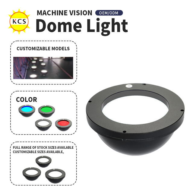
Traditional continuous dome lights represent the standard for ultimate optical diffusion. The mechanics involve a large physical hemisphere containing an upward-facing LED ring at its base. Light travels upward, strikes the hemispherical interior, and cascades evenly downward onto the target.
These units offer maximum illumination uniformity. They are the ideal choice for inspecting parts with deep recesses, extreme curves, or high topography. The physical wrap-around shape ensures that light reaches into cavities and illuminates steep vertical walls without casting shadows. However, their primary weakness lies in their large physical footprint. Traditional domes require significant Z-axis clearance above the inspection line. Furthermore, they demand close proximity to the part. Maintaining a short working distance is critical to preserving the "dome" effect over the entire Field of View (FOV). Moving the light too far away degrades its performance into that of a standard area light.
Machine Vision Flat Dome Lights
Space constraints on automated assembly lines often prohibit the installation of bulky hemispherical fixtures. Machine vision flat dome lights solve this exact mechanical problem. These units utilize a coaxial light path combined with a specialized micro-structured diffuser plate to simulate the dome effect without the physical bowl.
Edge-lit LEDs project light into a light guide plate, which directs the light downward through a highly engineered diffusion material. This setup solves clearance issues in tight mechanical envelopes. It effectively eliminates glare and hairline finish reflections on flat reflective objects. However, flat domes are less effective on highly curved or deep three-dimensional objects compared to traditional domes. Because they lack the physical wrap-around geometry, they cannot illuminate steep vertical walls or deep cavities as effectively. Additionally, the heavy diffusion materials often result in lower overall optical efficiency, requiring longer exposure times or higher camera gain.
Tunnel Lights (Cylindrical Dome Lights)
Tunnel lights adapt the dome principle for continuous inspection applications. The mechanics feature a half-pipe or cylindrical diffuser geometry designed to project a uniform line of diffuse light along a single longitudinal axis. Instead of a hemisphere, the light forms a continuous arch over the inspection zone.
These fixtures are perfect for continuous webs, long cylindrical components, cables, and extruded metal or plastic parts. They provide seamless, shadow-free illumination along the length of the moving product. The primary weakness is uneven light distribution on the longitudinal ends of the tunnel. Light escapes from the open ends, causing a drop-off in intensity at the edges of the FOV. Consequently, tunnel lights are entirely unsuitable for spherical or highly complex multi-axis parts that require omnidirectional light scattering.
Decision Matrix
Selecting the correct form factor requires balancing optical requirements against mechanical constraints. Use the following feature-to-outcome comparison framework to guide your specification process.
Form Factor | Ideal Part Geometry | Z-Axis Space Requirement | Working Distance Requirement | Primary Advantage |
|---|---|---|---|---|
Traditional Dome | Spherical, high topography, deep recesses | High (requires significant vertical clearance) | Short (must be mounted close to the part) | Maximum uniformity and omnidirectional diffusion |
Flat Dome | Flat reflective surfaces, slight curves | Low (slim profile fits tight spaces) | Short to Medium | Simulates dome effect in space-constrained envelopes |
Tunnel Light | Cylindrical, continuous extrusions, webs | Medium (requires clearance along one axis) | Short (mounted directly over the extrusion line) | Continuous uniform lighting for long or moving parts |
When to Specify a Dome Light: Success Criteria and Use Cases
Inspecting Highly Reflective Materials
Evaluating dome lighting for polished metals, glossy plastics, semiconductor wafers, and foil-sealed packaging requires understanding specular reflection. Directional lights create blown-out highlights on these materials, destroying image data in those regions. Dome illumination scatters the light, converting specular reflections into a uniform, glowing surface.
For semiconductor wafer inspection, even microscopic variations in lighting cause false defect detection. Dome lights provide the absolute uniformity required to inspect the mirror-like surface of bare silicon. Similarly, foil-sealed packaging often features wrinkles and varying angles of reflection. Diffuse illumination normalizes these variations, allowing cameras to inspect seal integrity and read printed batch codes without glare interference.
Eliminating Hairline Finish Glare
Machined metal parts frequently exhibit brushed textures or hairline finishes. Directional lighting catches these micro-grooves, creating high-contrast striations that confuse vision algorithms. Specialized flat dome lights effectively remove brushed metal textures and hairline finish glare.
By utilizing narrow-band wavelengths, such as Red LED lighting, combined with heavy diffusion, the light washes out the directional machining marks. The multi-directional photons penetrate the micro-grooves from all angles, eliminating the shadows that make the texture visible. This optical flattening exposes micro-scratches, surface contaminants, and actual defects that would otherwise remain hidden within the visual noise of the surface finish.
Curved Surfaces and High Topography
Directional lighting fails completely on cylinders and spheres, such as ball bearings or pharmaceutical vials. A directional light source creates a single, intense hotspot on the apex of the curve, leaving the edges in deep shadow. Dome lighting wraps light around these geometries to prevent hot spots.
The hemispherical shape of a traditional dome light ensures that photons strike the curved surface from angles corresponding to the part's curvature. This wrapping effect illuminates the entire visible hemisphere of a ball bearing evenly. For pharmaceutical vials, it allows the camera to inspect the liquid contents and glass integrity without the blinding glare typically caused by cylindrical glass containers.
OCR and Barcode Reading on Uneven Backgrounds
Optical Character Recognition (OCR) and 2D matrix decoding rely heavily on edge contrast. Shadows caused by embossed, stamped, or wrinkled backgrounds destroy this contrast, leading to read failures. Uniform diffuse lighting stabilizes these reading processes.
When reading a DataMatrix code laser-etched onto a cast aluminum part, the rough surface texture creates micro-shadows under directional light. Dome illumination fills in these micro-shadows, normalizing the background. The dark etched marks absorb the diffuse light, resulting in a crisp, high-contrast code that decoding algorithms can process reliably, regardless of the underlying surface topography.
Technical Evaluation Dimensions for Machine Vision LED Lighting
Wavelength and Color Selection
Selecting the correct wavelength is critical for maximizing contrast. Engineers must choose between monochrome (Red, Blue, IR, UV) and White light based on the target material. Matching the LED wavelength to metallic part features enhances contrast under diffuse conditions.
For example, using a 630nm Red dome light on a copper part will cause the copper to reflect the red light efficiently, appearing bright white to a monochrome sensor. Any surface oxidation or contamination will absorb the red light, appearing distinctly dark. Blue light (470nm) scatters more efficiently than red light, making it excellent for inspecting microscopic surface defects on silver or steel parts. Infrared (IR) dome lights are highly effective for penetrating printed inks on glossy packaging to inspect the underlying material without glare.
Intensity and Strobe Capabilities
Implementing heavy diffusion materials inherently causes significant light attenuation. Machine vision led lighting used in dome configurations must compensate for this loss. Address the inherent light loss caused by heavy diffusion and polarization filters by evaluating the necessity of high-current overdrive controllers.
On high-speed production lines, cameras require extremely short exposure times to freeze motion without blur. Standard continuous lighting often fails to deliver enough photons through the dome's diffuser during a 50-microsecond exposure. Strobing the LEDs—driving them with brief, high-current pulses—generates massive bursts of intensity. This technique freezes motion on high-speed lines while compensating for the optical inefficiency of the dome structure.
Aperture Sizing and Field of View (FOV) Constraints
The zenith aperture (camera viewing hole) presents a critical design constraint. Calculate the correct camera hole diameter to avoid vignetting while minimizing the unlit area directly above the part. If the aperture is too small for the chosen lens focal length and working distance, the edges of the hole will physically block the camera's view, causing dark corners in the image (vignetting).
Conversely, if the aperture is too large, it removes a significant portion of the reflective dome interior. This creates a large unlit void directly above the target, degrading the uniformity of the illumination. Engineers must match the lens angle of view precisely to the aperture diameter, ensuring clear sightlines while maximizing the internal reflective surface area.
Implementation Risks and Mitigation Strategies
The "Dark Spot" Effect
The most common implementation failure with dome lighting is the "dark spot" effect. This physical limitation occurs where the camera lens viewing hole reflects directly onto flat, mirror-like surfaces. Because the aperture is a physical hole, it emits no light. When inspecting a highly specular flat surface, the camera literally sees the reflection of its own dark lens.
Mitigation tactics require altering the optical geometry. Angling the part slightly (e.g., 5 to 10 degrees) shifts the reflection of the dark spot out of the camera's FOV. If angling the part is mechanically impossible, engineers must switch lighting strategies. Using coaxial lights for perfectly flat specular surfaces eliminates the dark spot entirely, as coaxial systems project light exactly along the camera's optical axis.
Working Distance Limitations
Dome lights obey strict working distance limitations. There is an inverse relationship between working distance and illumination uniformity. To maintain the "cloudy day" effect, the fixture must envelop the target. Moving a dome light too far from the object degrades it into a directional area light.
As the distance increases, the angles at which light strikes the part become narrower. The multi-directional scattering diminishes, and shadows begin to form. Engineers must design the mechanical handling system to allow the dome light to sit as close to the inspection target as physically possible, often within millimeters of the part surface.
Thermal Management
Enclosing high-output LEDs within a solid hemispherical structure creates significant heat dissipation challenges. Thermal management is critical for maintaining performance. As LED die temperatures rise, their optical output decreases, and their dominant wavelength can shift.
Thermal drift directly impacts light intensity and lifespan. A drop in intensity forces the camera to increase gain, introducing image noise. To mitigate this, industrial dome lights utilize heavy aluminum housings acting as passive heatsinks. For high-duty-cycle applications, engineers must ensure adequate ambient airflow around the fixture and strongly consider strobing the lights rather than running them continuously to minimize thermal load.
Environmental Contamination
Industrial manufacturing environments present severe contamination risks. Dust, cutting oil, and industrial grime easily accumulate on the internal reflective coating of traditional domes or the flat diffusers of space-constrained models. Contamination destroys the Lambertian reflectance, creating uneven lighting and false defects.
Mitigating this risk necessitates IP-rated enclosures in harsh environments. Specify fixtures with sealed, optically clear protective windows covering the bottom opening of the dome. While this introduces a slight risk of secondary reflections, it prevents grime from degrading the internal diffusion surfaces. Establish strict preventative maintenance schedules to clean the protective windows regularly using approved optical solvents.
Field Installation Steps for Dome Illumination
Proper physical installation dictates the success of the optical setup. Follow these exact steps when mounting a dome light on the production line.
Align the camera optical axis perfectly perpendicular to the inspection surface.
Mount the dome light fixture so the camera lens looks directly through the zenith aperture without touching the housing.
Lower the dome light until the bottom edge sits just above the tallest feature of the inspection part.
Adjust the camera focus and aperture settings to maximize depth of field while maintaining acceptable exposure.
Capture a test image of a perfectly flat mirror to identify the exact location and size of the dark spot reflection.
Tilt the part fixture 5 degrees off-axis to shift the dark spot out of the critical inspection zone.
Lock all mounting brackets using thread-locking fluid to prevent vibration-induced misalignment.
Conclusion
Dome lights remain the definitive solution for specular and complex-geometry inspection, provided the mechanical envelope allows for their integration. By converting directional point sources into omnidirectional, uniform illumination, these fixtures eliminate the glare and shadows that routinely defeat advanced vision algorithms. Understanding the physics of light scattering is essential for deploying reliable automated inspection on highly reflective materials.
When specifying a system, rely on strict shortlisting logic. Choose traditional domes for high spherical topography and deep recesses. Select tunnel lights for continuous cylindrical extrusion paths. Specify flat dome lights for space-constrained environments requiring inspection of flatter reflective surfaces with hairline finishes. Matching the geometry of the light to the geometry of the part is the foundation of optical success.
To ensure flawless integration, execute the following next steps:
Acquire representative sample parts from the production line for controlled lab testing under various diffuse lighting geometries.
Calculate exact FOV requirements, lens focal lengths, and maximum allowable working distances to prevent vignetting and dark spot reflections.
Request evaluation units from lighting manufacturers to validate contrast generation and thermal stability before finalizing the mechanical design.
Test high-current strobing capabilities if the production line speed requires exposure times under one millisecond.
FAQ
Q: Why is a dome light called "cloudy day illumination"?
A: The term refers to the optical analogy of sunlight being diffused by thick cloud cover. Just as clouds scatter the sun's directional rays to create shadowless, multi-directional light, the internal reflective coating of a dome light scatters LED light to illuminate a part evenly from all angles.
Q: What is the difference between a dome light and a ring light?
A: Ring lights provide directional, angle-specific illumination that highlights edges and surface textures, often causing glare on shiny parts. Dome lights provide indirect, highly diffused, uniform illumination designed specifically to eliminate glare and shadows on reflective or curved surfaces.
Q: Can machine vision flat dome lights replace traditional dome lights?
A: While flat dome lights save significant vertical space and eliminate glare on flat surfaces, they cannot fully replace traditional domes. They lack the physical hemispherical shape required to wrap light around deep curves, steep vertical walls, or complex three-dimensional topography.
Q: What is a tunnel light, and when is it preferred over a dome light?
A: A tunnel light features a cylindrical, half-pipe geometry rather than a hemisphere. It is preferred over a dome light when inspecting continuous webs, long extruded plastics, cables, or moving cylindrical parts that require uniform diffuse lighting along a single continuous axis.
Q: How do flat dome lights eliminate hairline finish glare on metal?
A: They utilize a coaxial light path combined with specialized micro-structured diffusion plates. This heavy diffusion, often paired with narrow-band wavelengths like Red LEDs, washes out the directional machining marks, flattening the surface optically to reveal underlying micro-scratches or defects.
Q: How do you eliminate the dark spot in a dome light image?
A: The dark spot is the reflection of the camera's viewing hole on a flat, mirror-like surface. Eliminate it by angling the part slightly to shift the reflection out of the field of view, or switch to a coaxial light source designed for perfectly flat specular surfaces.


