

Coaxial Light Vs Dome Light In Machine Vision
Views: 0 Author: Site Editor Publish Time: 2026-06-10 Origin: Site


In automated inspection, highly reflective or uneven surfaces easily cause glare, shadowing, and frustrating false rejects. Choosing the correct illumination geometry remains the single most critical factor in guaranteeing image acquisition stability. Engineers often debate between coaxial lights and dome lights. Both designs attempt to provide shadow-free, uniform illumination to eliminate bright spots. However, their underlying optical physics dictate entirely different ideal use cases, integration footprints, and working distances. Applying the wrong geometry can completely blind your sensor. This guide provides a direct, technical comparison of coaxial and dome illumination. We will help vision engineers evaluate necessary tradeoffs, minimize false-fail rates, and confidently specify the optimal machine vision light for complex visual inspection challenges. You will learn exact use cases, physical limitations, and how to conquer tricky surface topographies in modern manufacturing environments.
Key Takeaways
Coaxial lights are ideal for flat, highly specular surfaces (e.g., semiconductor wafers, bare PCBs, glass) where identifying subtle surface defects or engraved codes is necessary.
Dome lights excel at illuminating curved, wrinkled, or multi-faceted reflective surfaces (e.g., foil packaging, ball bearings, metallic cylinders) by bathing the object in multi-directional, diffuse light.
Standard coaxial illumination suffers from inherent light loss due to the internal beam splitter, often requiring a High Brightness Coaxial Machine Vision Light for high-speed imaging.
Dome lights require mounting very close to the inspection target, whereas coaxial lights offer more flexible standoff distances but are limited by their field of view (FOV).
1. Optical Principles: How Each Machine Vision Light Manipulates Photons
To master automated inspection, you must understand how different light sources bend and manipulate photons. Every target interacts differently under specific illumination geometries. coaxial light and dome light operate on entirely distinct physical principles.
Coaxial Light Mechanics
Coaxial illumination relies on a clever internal arrangement. It utilizes a half-mirror, commonly called a beam splitter. Manufacturers angle this mirror precisely at 45 degrees. The LED source sits perpendicular to the camera axis. Light hits the beam splitter and redirects downwards. It travels onto the object on the exact same optical axis as the camera lens.
When this light strikes a perfectly flat, mirrored surface, it bounces straight back. The reflected photons pass through the half-mirror and enter the camera sensor. The flat surface appears brilliant and white. However, slanted features or uneven textures scatter light away from the lens. The camera cannot capture these scattered photons. Consequently, dents, scratches, or raised edges appear sharply dark against a bright background. This specific filtering effect makes it an incredibly powerful tool for topological defect detection.
Dome Light Mechanics
Dome lights tackle reflection issues using the integrating sphere principle. The unit features a highly reflective, matte-white dome cavity. The LEDs point upward into this cavity rather than downward. The curved white surface scatters the photons. It bounces them onto the target object from every possible spatial angle.
This creates a perfect "cloudy day" effect. Multi-directional diffuse light wraps around the target. It virtually eliminates shadows. It neutralizes specular glare regardless of the object's surface geometry. Complex shapes receive perfectly uniform illumination.
The "Camera Hole" Caveat
You must watch out for a critical physical limitation. Dome lights require a top aperture so the camera can see the target. We call this the "camera hole." If you inspect perfectly flat, highly reflective surfaces under a dome, you will see a problem. The camera hole reflects directly back into the lens. It appears as a distinct dark, unlit spot right in the center of your image. Coaxial lighting naturally prevents this specific flaw. The beam splitter ensures no dark voids exist in the optical path.
2. Surface Geometry & Material Defect Evaluation
Choosing the correct geometry depends entirely on the material topography. You must evaluate the surface finish before selecting a fixture.
When to Specify Coaxial Light
You should lean toward coaxial solutions when dealing with flat specular surfaces. Silicon wafers, polished aluminum, glass slides, and flat mirrors require this exact optical geometry. The technique acts as an optical flatness filter.
It excels at highlighting minute topological changes. Direct Part Markings (DPM) on shiny metals become highly legible. A laser-etched barcode scatters the perpendicular light. The etched lines appear starkly black. The surrounding flat metal appears uniformly white. This extreme contrast guarantees reliable barcode reading.
Best Practices for Coaxial Application:
Align the camera perpendicular to the target surface.
Ensure the target remains perfectly flat during continuous web inspections.
Avoid using this method for objects featuring heavy spherical curves.
When to Specify Dome Light
You must specify dome illumination for curved, wrinkled, or multi-faceted specular surfaces. Think of glossy pharmaceutical blister packs. Consider crinkled metallic foils or spherical ball bearings. Coaxial illumination fails here. The curved surfaces scatter straight light away from the lens. The image simply turns black.
Dome lights bathe these curves in diffuse energy. They homogenize the background. This makes them ideal when your primary goal is reading printed text on uneven glossy surfaces. The multi-directional photons ensure the underlying topography does not create blinding glare hotspots. Inkjet printing on a curved aluminum can becomes perfectly legible.
Common Mistakes to Avoid:
Using a dome light to read deep engraved features. The diffuse light fills the engravings, destroying contrast.
Using a dome for flat mirrors, which inevitably captures the dark camera hole reflection.
3. Implementation Realities: Footprint, Working Distance, and Light Loss
Theoretical physics means little without practical integration. You must consider machine constraints, working distances, and optical efficiency.
Working Distance Constraints
Dome lights demand extreme proximity to the target. You often mount them within millimeters of the object. If you raise a dome light too high, the diffuse "wrapping" effect degrades. The light essentially becomes a standard ring light. This extreme proximity causes severe mechanical headaches. It easily interferes with robotic pick-and-place tooling. Clearance becomes severely limited.
Coaxial units offer much more flexible standoff distances. You can mount them further away from the inspection plane. This provides safer tool clearance for automated arms and grippers. However, coaxial housings are generally bulkier. They also face strict field of view (FOV) limitations. The internal mirror must be larger than the required FOV. Inspecting a massive area requires an equally massive, heavy coaxial fixture.
The Brightness Tradeoff
Standard coaxial illumination suffers from massive inherent optical inefficiency. The 45-degree beam splitter causes severe light loss. Physics dictates this penalty. Let us examine the photon journey.
First, the LED emits light toward the half-mirror. The mirror reflects 50% of this light downward. It transmits the other 50% into the housing body, wasting it. The remaining 50% hits the target and bounces back. It hits the mirror again. The mirror transmits 50% of that returning light to the camera. It reflects the other half back toward the LED. Ultimately, a standard coaxial unit loses approximately 75% of its total potential light output.
Light Attenuation Chart
The following chart illustrates the dramatic optical loss inherent to beam splitter geometries.
Optical Stage | Photon Path | Light Retained | Light Lost |
|---|---|---|---|
Stage 1: Emission | LED source hits the 45-degree beam splitter. | 50% (Directed to target) | 50% (Absorbed by housing) |
Stage 2: Reflection | Target reflects light back to the beam splitter. | 100% of remaining (Assuming flat mirror) | 0% |
Stage 3: Transmission | Light passes through splitter to the camera sensor. | 25% (Total system remaining) | 25% (Reflected back to LED) |
Total System Yield | End-to-End | ~25% | ~75% |
High-speed line-scan applications cannot survive this photon penalty. Fast-exposure area scan applications also struggle. To resolve this, vision engineers heavily rely on specifying a High Brightness Coaxial Machine Vision Light. These specialized units feature advanced thermal management. They utilize high-density LED arrays to aggressively compensate for the inherent optical loss. You must deploy them whenever microsecond exposure times are mandatory.
4. Advanced Alternatives: Resolving Edge-Case Limitations
Standard fixtures cannot solve every inspection challenge. Complex machine envelopes often demand specialized optical solutions. Industry manufacturers have developed advanced alternatives to overcome standard geometry limits.
Coaxial-Dome Hybrid Solutions
Some modern targets exhibit both flat mirrored sections and highly curved edges. Neither standard option works perfectly. Hybrid fixtures combine a dome shape with a coaxial insert located at the top camera aperture. The coaxial module injects straight light down the center. This brilliantly eliminates the dreaded "dark spot" effect on flat glossy items. Meanwhile, the surrounding dome maintains multi-directional diffuse light for the curved edges. This hybrid approach delivers complete uniformity.
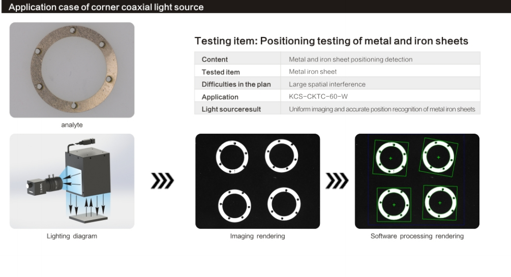
Corner Coaxial Innovations
Mechanical clearance often dictates the vision system design. Sometimes you simply lack the vertical Z-axis space to mount a bulky straight-down coaxial housing. A traditional housing stacks the camera, lens, and beam splitter vertically. This stack can easily exceed 200 millimeters.
To solve this, vision engineers specify a Corner Coaxial Light. This specialized variant targets ultra-tight machine envelopes. It allows illumination to be injected at an angle. It often uses a 90-degree folded optical path. You preserve the crucial coaxial filtering effect while solving strict volumetric constraints. It fits perfectly into compact inspection cells. You achieve flawless flat-surface inspection without redesigning the entire machine frame.
5. Engineer’s Decision Framework: Shortlisting the Right Light
Guessing causes delays and inflates engineering hours. You need a systematic approach to hardware selection. Follow this sequential framework to specify the correct geometry rapidly.
Assess Topography: Examine the highly reflective surface. Is it mostly flat? You should lean toward coaxial solutions. Is it curved, wrinkled, or multi-angled? You must lean toward a dome fixture.
Check Clearances: Evaluate your mechanical CAD model. Does your setup allow the light to sit almost flush with the part? If yes, a dome is highly viable. Do you need more than 50 millimeters of clearance for automated arms? Coaxial is strongly preferred.
Define Output Requirements: Review your camera exposure times. If you inspect high-speed flat substrates, remember the 75% light loss rule. Ensure your power budget accommodates high-brightness coaxial modules to freeze motion effectively.
Proof of Concept (PoC): Never finalize a bottom-of-funnel decision based purely on theory. You must lab-test both geometries on actual production samples. This is the only way to evaluate edge-case glare.
Decision Matrix Summary
Use this reference table to validate your logic during the design phase.
Evaluation Criteria | Coaxial Illumination | Dome Illumination |
|---|---|---|
Target Surface Topography | Strictly flat, highly reflective. | Curved, wrinkled, uneven. |
Primary Defect Type | Dents, scratches, laser DPM. | Surface print on foil, generic stains. |
Required Working Distance | Medium to High (Flexible). | Extremely Low (Flush to target). |
Light Efficiency | Low (~25% transmission). | High (High efficiency scattering). |
Size / Footprint Limit | Scales massively with FOV. | Compact, but wide diameter. |
Trust the physics. If you misalign the optical principle with the material topography, no amount of software processing will recover the lost image data.
Conclusion
Neither lighting geometry is universally superior. Their efficacy is entirely dictated by the target's specific shape and the mechanical constraints of your inspection cell. Coaxial lighting acts as an unmatched optical filter for flatness. It perfectly highlights deviations, scratches, and etchings on specular substrates. Conversely, dome lighting acts as the ultimate equalizer for unevenness. It wraps complex curved targets in soft, shadowless energy.
Your next steps are strictly practical. First, review your machine clearance requirements in CAD. Second, calculate your required exposure times to freeze motion. If you need intense bursts of light, upgrade immediately to high-brightness models. Finally, request loaner units from your vision partner. Conduct empirical testing on live production samples. Proper physical validation prevents costly integration failures downstream.
FAQ
Q: Why is my coaxial light producing a dim image compared to my ring light?
A: The internal beam splitter inherently causes massive optical attenuation. The light loses 50% of its intensity bouncing down to the part, and another 50% returning to the camera. You lose roughly 75% total. To fix this, you must upgrade to high-brightness LED variations, open your lens aperture, or increase camera exposure time.
Q: Can a dome light inspect flat, mirrored surfaces?
A: Yes, but with a major limitation. The top viewing hole allowing the camera to see the part will reflect directly back into the lens. This creates a distinct dark circle in the exact center of your field of view. Coaxial geometry prevents this completely.
Q: What is a Corner Coaxial Light used for?
A: Engineers use it when they desperately need the optical benefits of a coaxial setup, but lack the vertical Z-axis clearance above the part. It alters the mechanical footprint. The light injects from an angle, fitting into tight machinery where standard straight-down housings simply will not fit.


