

Best Back Light Options For Machine Vision Systems
Views: 0 Author: Site Editor Publish Time: 2026-06-08 Origin: Site


In industrial inspection, software algorithms are only as reliable as the image contrast they process. For dimensional measurement and edge detection, selecting the correct back light is the most critical hardware variable. Specifying an underpowered or incorrectly sized illumination source leads to edge blooming, inconsistent measurements, and high false-reject rates. Engineers sometimes overlook how vital the background light field is to achieving reliable sub-pixel accuracy. Poor illumination fundamentally degrades data before the software even begins its analysis.
This guide provides an objective, engineering-focused framework for evaluating, shortlisting, and implementing these crucial optical components. You will learn how to match wavelengths, select the proper physical geometry, and avoid common integration pitfalls in automated setups. By applying these principles, you can eliminate environmental variables and build a highly robust inspection environment.
Key Takeaways
Contrast over brightness: Effective silhouetting relies on matching the backlight’s wavelength and uniformity to the specific target material, not just maximizing lumen output.
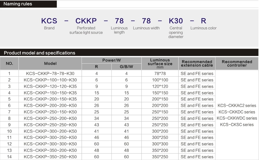
Geometry dictates selection: Standard flat panels work for most setups, but complex mechanical envelopes often require a Customizable Hole Machine Vision Backlight Source to accommodate tooling or optics.
System synergy is non-negotiable: A high-end machine vision light will fail if not correctly paired with appropriate lensing (e.g., telecentric) and ambient light filtration.
Bench-testing is mandatory: Theoretical specifications must be validated against real-world line speeds and exposure times before full-scale deployment.
Framing the Problem: Success Criteria for Vision Backlighting
The primary business goal in any automated inspection setup is reducing false negatives in defect detection. We also aim to ensure sub-pixel accuracy in metrology applications. These two factors directly impact factory throughput and stringent quality compliance. When you cannot trust your measurement data, the entire automation line suffers from inefficiencies and constant manual intervention.
Backlights fulfill a very specific core function. They create a high-contrast silhouette by illuminating the subject from behind. This active background lighting completely suppresses surface details on the target. We do this to heavily emphasize outer edges, geometric profiles, and internal fluid levels. By eliminating distracting surface textures, the vision algorithms can run faster and with much higher confidence.
To evaluate a lighting solution objectively, we rely on three stringent success metrics. Every selected component must excel in these specific areas to guarantee long-term reliability.
High optical uniformity: The illumination field must remain consistent across the entire active area. You typically need uniformity greater than 80% to 90%. Any hot spots or dark zones will trick the software into measuring false edge gradients.
Stable thermal management: Light-emitting diodes generate localized heat. If you fail to dissipate this heat, the emission intensity degrades over time. Color wavelengths can also shift under high thermal loads. Stable chassis cooling prevents these degradation issues.
Sufficient output intensity: High-speed production lines require incredibly brief camera exposure times. Microsecond exposures prevent motion blur. Your illumination source must output enough photons to saturate the sensor during these tiny time windows.
Primary Categories of Machine Vision Backlights
Standard Diffuse Backlights (Edge-Lit vs. Direct-Lit)
Diffuse lighting scatters photons evenly across the active viewing area. This creates a soft, uniform background. Manufacturers generally build diffuse panels using two distinct architectural methods: edge-lit and direct-lit. Understanding the mechanical differences helps you optimize your specific machine layout.
Edge-lit panels feature LED strips mounted along the internal perimeter of the frame. A specialized light guide plate directs the photons outward toward the camera. This architecture allows for a remarkably thin form factor. They prove ideal for cramped machine spaces where clearance remains minimal. However, because the LEDs sit on the edge, the maximum intensity remains lower than other configurations.
Direct-lit panels, often called array lights, place a dense grid of LEDs directly behind a diffusing material. This approach delivers significantly higher intensity and long-term durability. We prefer direct-lit arrays for high-speed webs or inspecting highly dense, semi-opaque parts. They do require a thicker physical housing to accommodate the matrix and heat sinks.
Feature | Edge-Lit Architecture | Direct-Lit Architecture |
|---|---|---|
Form Factor | Very thin profile, lightweight. | Thicker profile, heavier housing. |
Uniformity | Excellent, highly consistent field. | Good, but requires quality diffusers. |
Max Intensity | Moderate (limited by perimeter space). | Very High (dense LED matrix). |
Best Use Case | Tight mechanical constraints. | High-speed lines, short exposures. |
Collimated Backlights
Collimated units feature parallel light rays rather than scattered, diffuse light. Optical engineers design these components using specialized lenses or micro-louvers. These structures force every photon to travel in a strictly parallel path toward the camera sensor. This physical property solves a massive problem in precise metrology.
They are absolutely essential for inspecting highly reflective cylindrical parts, threaded fasteners, or clear glass vials. When you use diffuse light on a curved metal surface, the scattered rays reflect off the curve and bounce directly into the lens. We call this the "wrap-around" effect. It artificially erodes the silhouette, making the cylinder look smaller than reality. Collimated rays strike the curve and block entirely, producing a razor-sharp, true-dimension edge.
Best Practice: You must strictly pair collimated units with telecentric lenses. Standard entocentric lenses view subjects at an angle, which ruins the parallel light advantage. Telecentric lenses only accept parallel rays, ensuring perfectly accurate dimensional scaling across the entire field of view.
Specialty and Custom Geometries
Standard rectangular panels work perfectly for most traditional conveyor setups. However, complex automation environments often introduce rigid mechanical envelopes. You might face situations where a robotic arm, a pneumatic gripper, or the camera itself must occupy the exact center of the illumination field.
This is where a Customizable Hole Machine Vision Backlight Source becomes highly valuable. Manufacturers can engineer active panels with precise cutouts. These bespoke geometries allow your mechanical tooling to pass directly through the light plane. Crucially, they achieve this without sacrificing the uniform background illumination field surrounding the object. You maintain perfect silhouetting while solving complex mechanical integration headaches.
Key Evaluation Dimensions for Industrial Specifications
Wavelength and Target Material
Selecting the correct color wavelength is just as critical as choosing the form factor. White light is common, but monochromatic light often yields far superior contrast. You must analyze the target material to make an informed decision.
Infrared (IR) wavelengths offer unique penetration properties. IR proves ideal for piercing through specific opaque plastics. This allows the vision system to see internal components or fluid levels hidden from the naked eye. Furthermore, IR light often ignores printed dyes on packaging. If you need to measure the edge of a bottle without letting printed labels confuse the software, IR removes the printed noise completely. It also heavily minimizes the impact of ambient factory lighting.
Red or blue wavelengths are selected based on the target's specific color. You use a wavelength to either absorb or transmit light. Blue light features a shorter wavelength, making it scatter slightly more. It provides excellent resolution for detecting microscopic edge defects. Always check your specific camera sensor's spectral sensitivity curve to ensure it reacts well to your chosen wavelength.
Active Area vs. Field of View (FOV)
Proper physical sizing prevents data skewing. The active illuminating area must completely cover the camera's intended field of view. However, simply matching the dimensions exact-to-exact leads to optical issues.
Rule of thumb: The backlight's active area must extend significantly beyond the camera's FOV. We generally recommend oversizing the active area by at least twenty percent in all directions. Undersizing leads to immediate edge darkening. The light drops off near the perimeter, creating severe vignette effects. When the background turns gray at the edges, software measurements skew rapidly, causing false rejects on perfectly good parts.
Duty Cycle and Overdriving
How you power the device determines its lifespan and maximum intensity. Engineers evaluate two primary modes: continuous wave (CW) operations versus strobed operations. Continuous wave simply leaves the panel turned on at a constant power level. This works well for slow-moving indexing tables.
High-speed manufacturing demands a different approach. Strobing synchronizes the illumination pulse with the camera's microsecond exposure window. Using an advanced controller, you can force an Industrial Machine Vision LED Backlight Source to overdrive. Overdriving pushes three to five times the nominal current through the LEDs for a tiny fraction of a second. This generates an incredibly intense burst of photons, perfectly freezing motion on high-speed webs. Because the pulse is so brief, the LEDs do not overheat, heavily preserving the unit's long-term lifespan.
Implementation Realities and Common Pitfalls
Edge Blooming (Light Wrap)
Over-saturating the camera sensor creates a frustrating phenomenon known as edge blooming. When a background panel is far too bright, the individual pixel wells on the CMOS sensor fill up with photoelectrons. The excess charge spills over into adjacent darkened pixels.
This physical pixel spillover diffuses the sharp edges of the target. A crisp boundary becomes a soft, blurred gradient. Consequently, the edge detection software miscalculates the boundary line. This effectively reduces the measured dimensions of the part. Always begin integration at lower intensity levels. Slowly dial up the power until you reach an optimal grayscale threshold without causing pixel saturation.
Mounting and Clearance Constraints
Mechanical design teams frequently prioritize material handling hardware over optical components. Rigid mechanical envelopes often clash with the thermal housing requirements of your selected lighting. High-output direct-lit arrays generate substantial heat.
Common Mistake: Trapping a high-intensity panel inside a sealed metal bracket without airflow. Heat buildup will quickly degrade the LED chips, causing a drop in intensity and a shift in color. Heat dissipation space must be actively factored into the early CAD design. Utilize aluminum extrusion mounts to act as conductive heat sinks.
Ambient Light Interference
Factory environments present chaotic lighting conditions. Skylights change intensity based on cloud cover. Forklifts drive past the inspection station with bright headlights. Neighboring weld cells create intense flashes. Relying solely on your panel's intensity to drown out this ambient noise is a risky strategy.
Implementing optical bandpass filters is a required defensive measure. You match the filter exactly to the panel's emission wavelength. If you use a 660nm red source, you install a 660nm bandpass filter on the camera lens. The filter physically blocks the chaotic factory lighting, allowing only your highly controlled background illumination to reach the sensor. This guarantees consistent contrast across all factory shifts.
Shortlisting Logic: Specifying Your Vision Illumination
Selecting the optimal machine vision light requires a structured, logical approach. Guessing based on spec sheets alone leads to costly redesigns. Follow this specific sequential framework to ensure reliable system synergy.
Define the optical requirements: Map out the required field of view and the necessary optical resolution. Analyze the target geometry closely. If the part blocks the center axis, this analysis determines whether a standard flat panel or a custom hole geometry is fundamentally required.
Calculate intensity requirements: Base your intensity needs on the physical physics of the production line. Determine the maximum line speed. Calculate the required depth of field, which dictates your lens aperture setting. A smaller aperture demands more light. These variables determine the resulting maximum exposure time. Short exposures require massive illumination intensity.
Determine the illumination technique: Decide carefully between a diffuse setup or a collimated setup. If the task is general presence/absence detection or measuring flat opaque objects, diffuse is perfectly fine. If the task involves precision metrology on curved, threaded, or reflective surfaces, you must specify collimated optics.
Request validation units: Never procure fleet volumes based solely on theoretical data sheets. Specifications look perfect on paper but often interact unpredictably with real-world target materials. Request sample units from the manufacturer. Conduct thorough bench-testing under the exact environmental conditions, matching the target line speeds and filtering out ambient interference.
Conclusion
Lighting is never just a peripheral accessory in automation; it remains the foundational data source for any vision algorithm. If you feed poor contrast into a high-end processor, you will still receive inconsistent results. The right illumination strategy actively removes variables from your inspection environment rather than adding them. It creates a stable, repeatable baseline for every measurement.
Your next step should be auditing your current processes. Review your system's false-reject logs to identify patterns related to contrast failures or edge detection errors. Map the physical constraints of your stations. Finally, consult directly with an illumination specialist to test specific wavelengths, evaluate custom form factors, and run bench trials against your exact production parts.
FAQ
Q: When should I use a collimated back light instead of a standard diffuse one?
A: Use collimated lights for precise dimensional measurements of cylindrical, curved, or thick transparent parts. In these scenarios, standard diffuse light would bend around the edges and blur the true boundary. Collimated parallel rays eliminate this wrap-around effect entirely, providing crisp, sub-pixel accurate silhouettes.
Q: How do I manage heat in high-intensity back light applications?
A: Utilize strobing rather than continuous operation. Pulsing the light only when the camera exposes prevents heat buildup. Additionally, ensure the mounting chassis incorporates conductive heat sinking, avoiding sealed enclosures that trap thermal energy.
Q: Can I use an infrared (IR) back light for transparent or semi-transparent parts?
A: Yes, IR is highly effective at penetrating printed dyes or certain opaque plastics. This allows the vision system to clearly see internal features or fluid levels while completely ignoring surface-level printed noise and ambient factory lighting interference.


