

Back Light Vs Front Light In Machine Vision
Views: 0 Author: Site Editor Publish Time: 2026-06-12 Origin: Site


Lighting geometry acts as the absolute foundation of machine vision accuracy. You cannot fix poor physical contrast by relying purely on software algorithms. This software-heavy approach remains a high-risk, low-yield strategy for manufacturing lines. Engineers frequently face deep decision paralysis when selecting between back lighting and front lighting setups. You must routinely navigate extremely tight mechanical constraints. Highly reflective machined parts add severe inspection complications. Furthermore, high-speed inspection lines leave zero margin for processing error.
Making the wrong illumination choice leads to endless software debugging and unacceptable false reject rates. This guide provides a direct, technical evaluation framework for comparing these essential lighting geometries. We prioritize reliable feature extraction above all else. You will learn to handle physical integration realities seamlessly. You will also understand how to ensure long-term system scalability without compromising on inspection accuracy.
Key Takeaways
Contrast Generation: Back lighting creates high-contrast silhouettes ideal for edge detection, while front lighting excels at surface topography and defect inspection.
Implementation Constraints: Mechanical space, heat dissipation, and working distance often dictate lighting geometry before optical requirements are even considered.
Advanced Customization: Specialized formats, such as a Customizable Hole Machine Vision Backlight Source, bridge the gap between back and front lighting constraints in complex mechanical assemblies.
Total Cost of Ownership: Energy-efficient options like a Low Power LED Backlight for Vision Inspection mitigate thermal interference and reduce long-term operating costs.
Fundamental Geometry: How Light Interaction Defines Contrast
Selecting the correct machine vision light geometry sharply reduces false rejects on the factory floor. It heavily lowers the computational load placed on your vision software. Front lighting mechanics depend entirely on light reflecting off the target object. The photons bounce off the material surface and enter the camera lens. You can configure this reflection using brightfield or darkfield setups depending on the angle. This geometric approach highlights surface textures beautifully. It exposes vibrant colors and reveals minute topological anomalies.
Conversely, a back light operates on a completely different physical principle. It relies on light traveling past the extreme edges of the target. Light can also travel directly through a translucent target before hitting the lens. This specific interaction creates a stark black-and-white binary silhouette. It works perfectly by exploiting object opacity rather than surface reflectivity.
We must establish a crucial trust node here. Neither lighting geometry proves universally superior. Your ultimate choice depends entirely on the specific physical feature you must inspect. You must critically evaluate whether you are looking for distinct geometric edges or complex surface details. Software algorithms simply process the pixel data they receive. If the physical light interaction does not create stark contrast, the algorithm will eventually fail.
Contrast Generation Comparison
Geometry Type | Primary Mechanism | Ideal Inspected Features | Common Limitations |
|---|---|---|---|
Front Lighting | Reflection off the target surface | Textures, colors, barcodes, scratches | Highly susceptible to ambient glare and part tilt |
Back Lighting | Transmission past or through the target | Outlines, threads, clear fluids, gaps | Cannot reveal any surface details or print |
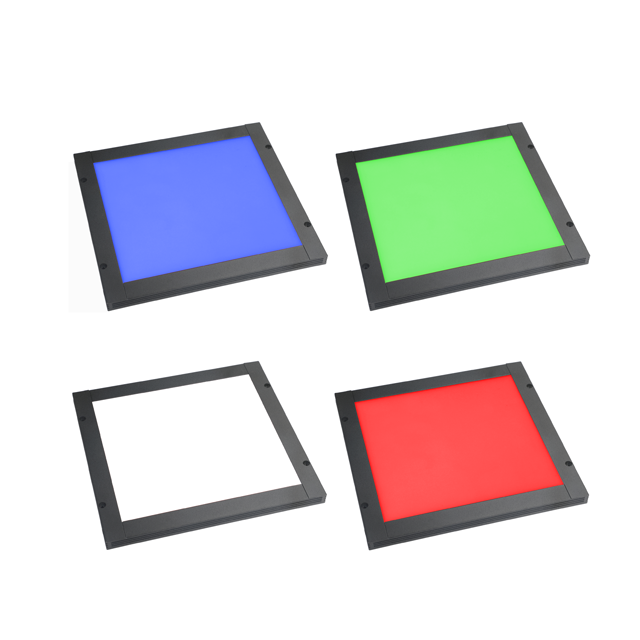
When to Specify Back Lighting for Machine Vision
Primary applications for silhouette illumination include precise edge detection and high-accuracy measurement. Metrology systems rely heavily on this exact geometry. It also dominates simple presence or absence verification tasks across automated assembly lines. When you need to measure the exact pitch of a machined screw thread, this geometry performs flawlessly.
The technical advantages are massive. This setup completely eliminates frustrating surface noise. Scratches, random color variations, and unpredictable reflections easily confuse edge-detection algorithms like Sobel or Canny operators. Back lighting immediately strips away these disruptive visual variables. It provides a clean, binary image. It also delivers the highest possible contrast for transparent or translucent object inspection. For example, you can reliably detect clear fluid levels inside glass medical vials. The liquid refracts the light differently than empty space, creating a distinct, trackable dark line.
Implementation realities demand experienced engineering oversight. You must always watch out for "light wrap." This optical phenomenon happens when light diffracts around cylindrical shapes. It also occurs around highly reflective curved edges. Light wrap can severely distort your precise dimensional measurements, causing parts to appear smaller than reality. Furthermore, spatial constraints often complicate factory integrations. Backlights require dedicated physical space directly behind the inspected part. Depending on your conveyor belt or mechanical fixture design, this placement is not always mechanically feasible. You cannot magically create space inside a crowded machine chassis.
Best Practices for Silhouette Inspection
Always pair collimated illumination with telecentric lenses to combat edge diffraction.
Ensure the illuminated area extends at least 10% beyond the largest possible part dimension.
Use monochrome cameras rather than color sensors to maximize edge sharpness and reduce interpolation errors.
When Front Lighting is the Mandatory Choice
Sometimes, frontal illumination represents your only viable option. Primary applications heavily involve intricate surface defect detection. You need it to find tiny micro-scratches, material porosity, or subtle tooling marks on metal components. It also rules supreme for Optical Character Recognition (OCR) and 2D matrix barcode reading tasks. Color verification and complex electronic assembly checks absolutely require front illumination to succeed.
You must carefully consider several critical variations to match your specific material:
Coaxial/On-Axis: This variation works best for flat, highly specular surfaces. It handles mirror-like finishes perfectly by projecting light down the exact optical axis of the camera.
Low-Angle Darkfield: This setup emphasizes surface topological defects. By grazing the surface at a shallow angle, it easily highlights microscopic dust particles or raised metal edges against a dark background.
Dome Lighting: This design creates a uniform, "cloudy-day" effect inside an integrating sphere. This variation brilliantly eliminates harsh shadows on complex, curved geometries.
Front lighting remains highly susceptible to ambient factory light interference. Changes in part presentation cause massive reliability issues. A slight part tilt can completely alter the reflection angle. This microscopic tilt instantly breaks your inspection algorithm, throwing false negatives. You must strictly control the mechanical part presentation mechanism to ensure repeatable reflections.
Common Mistakes to Avoid
Mounting ring lights too close to reflective parts, creating blown-out "hotspots" that blind the sensor.
Ignoring factory floor lighting. Always use bandpass filters to block overhead fluorescent or LED factory glare.
Relying on standard diffuse lights to read laser-etched codes on brushed metal; use coaxial instead.
Evaluation Criteria for Lighting Selection
Use a strict Feature-to-Outcome Matrix when beginning your design phase. If you are inspecting outer outlines, dimensional tolerances, or fluid fill levels, specify back lighting. If you are inspecting surface integrity, print legibility, or color accuracy, specify front lighting. Sticking to this matrix prevents fundamental architecture errors.
Mechanical and spatial considerations carry heavy weight in real-world engineering. Always evaluate your exact working distance and fixture clearance early. If a continuous backlight isn't possible due to complex tooling, explore specialized optical solutions. You can easily integrate a Customizable Hole Machine Vision Backlight Source. This highly adaptable design allows cameras, sensors, or mechanical pick-and-place grippers to pass directly through the lighting plane. It gracefully solves severe mechanical interference problems without sacrificing contrast.
Power and thermal management require rigorous attention. High-intensity LEDs generate substantial thermal output at the semiconductor p-n junction. This heat can cause mechanical expansion in tight camera enclosures. Heat also rapidly degrades LED lifespan and shifts the emitted color spectrum. To mitigate this severe physical risk, specify a Low Power LED Backlight for Vision Inspection. Alternatively, you can utilize hardware strobe controllers for front lights. Both hardware methods manage thermal output brilliantly. They achieve excellent thermal stability without sacrificing your required ultra-short exposure times.
Wavelength matching plays a critical role in system stability. Pairing the light’s specific wavelength with dedicated bandpass filters drastically optimizes contrast. You might choose Red, Blue, or Infrared spectrums depending on the material's absorption properties. This optical filtering technique blocks ambient factory light entirely. It holds true regardless of whether you use a front or back geometry.
Shortlisting Logic & Risk Mitigation
Use a systematic approach to eliminate integration risks before you finalize your bill of materials. Guessing creates unacceptable vulnerabilities.
Step 1: Prototype with a Vision Lab. Never commit to a lighting geometry without testing physical part samples. Test them under both distinct setups on a controlled bench. Theoretical contrast rarely matches harsh factory floor realities. Material finishes vary wildly from CAD models.
Step 2: Assess Mechanical Interference. Consult your mechanical engineering teams early in the design phase. Ensure the chosen light housing actually fits within the rigid machine design. Account for cable routing, mounting brackets, and moving robotic arms.
Step 3: Evaluate Software Impact. Test how the chosen lighting handles difficult edge cases. Introduce lubricating oil, factory dust, or variable metal finishes on a test part. Ensure your AI or vision algorithm remains robust under these artificially degraded conditions.
We strongly recommend engaging an illumination specialist as your immediate next step. Conduct a thorough physical proof-of-concept test using your actual production parts. Do not blindly purchase expensive lights based solely on manufacturer datasheet specifications. Datasheets show ideal conditions; factories provide the exact opposite.
Conclusion
The decision between front and back lighting remains a fundamental engineering trade-off. You must skillfully balance the need for intricate surface detail against the requirement for crisp edge contrast. The most advanced camera sensor on the market cannot mathematically compensate for incorrect lighting geometry. High-quality physical contrast always outperforms desperate software corrections. We urge you to take proactive, evidence-based steps during your design phase. Schedule a technical consultation with an optics expert early in the project. Request a physical evaluation unit for your laboratory. Alternatively, submit your tricky part samples for a custom lighting feasibility study. Getting the physics right guarantees your inspection system will run flawlessly for years.
FAQ
Q: Can a back light be used for surface inspection?
A: Generally no, because it creates a dark silhouette by blocking light. However, for highly transparent materials like glass or clear plastics, backlighting can effectively highlight internal surface defects. Bubbles, cracks, or material inclusions become highly visible dark spots through light refraction and scattering.
Q: How do I prevent "light wrap" when using a back light for measurement?
A: You should use a collimated illumination source. This specific configuration ensures all light rays travel perfectly parallel, rather than scattering in multiple directions like a standard diffuse panel. Pairing a collimated light with a telecentric lens effectively eliminates wrap, distortion, and perspective errors.
Q: What is the easiest way to manage heat in machine vision lighting?
A: Use hardware strobing to pulse the LEDs only when the camera triggers an exposure. This prevents continuous heat buildup. Alternatively, select purpose-built, low-power LED modules designed specifically for high-efficiency thermal output when operating inside tight, unventilated machine enclosures.


