

Top Spot Light Applications In Machine Vision Inspection
Views: 0 Author: Site Editor Publish Time: 2026-06-05 Origin: Site


Automated inspection systems rely completely on quality image capture. Suboptimal lighting remains the primary cause of false rejects. It destroys system reliability entirely. Engineers often default to standard illumination setups. They quickly realize these fail under complex spatial constraints. While ring and bar lights dominate general applications, they struggle elsewhere. Specific spatial constraints demand highly focused illumination. Tight working distances and strict optical requirements necessitate a different approach. We must look beyond broad-area floodlighting. This article analyzes the precise operational scenarios where focused point illumination excels. These compact units easily outperform other form factors in specific engineering cases. You will learn the exact evaluation criteria necessary to specify your hardware. We will help you evaluate optimal performance markers. You can then confidently select the right solution. You will avoid over-engineering your industrial vision system.
Key Takeaways
Spot lights are uniquely suited for long-distance illumination, confined integration spaces, and pairing with specialty optics like coaxial lenses.
Upgrading to a collimated point light reduces beam divergence, creating razor-sharp silhouettes crucial for high-precision edge detection.
Evaluating an industrial LED spot light for vision requires balancing optical intensity with thermal management capabilities to ensure continuous-duty lifespan.
Mitigating glare and "hotspots" requires precise angular adjustment, often necessitating secondary diffusers or polarizing filters.
Defining the Operational Baseline: When to Specify a Spot Light
You cannot solve every automated inspection problem using a massive dome. General-purpose fixtures occupy too much volume. Sometimes the physical envelope simply cannot accommodate bulky enclosures. Think about robotic end-effectors navigating tight conveyor housings. You face severe space limitations on the factory floor. A compact lighting footprint becomes absolutely mandatory. Standard diffused arrays fail in these cramped environments.
Next, consider your working distance challenges. Diffused arrays suffer heavily from the inverse-square law. Their light degradation over distance ruins image contrast rapidly. A dedicated spot light overcomes this severe drop-off. It pushes focused photons exactly where you need them most. The intense beam maintains usable luminosity over much longer physical throws. You achieve bright images without moving the fixture closer to the target.
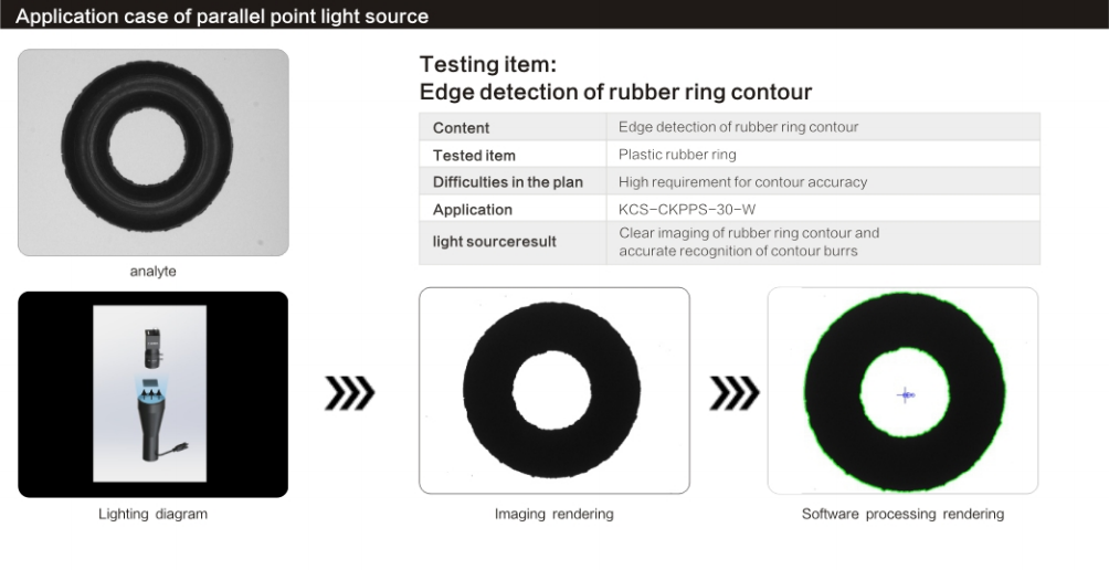
Finally, you must understand the collimation factor. Standard focused lighting has some minor beam spread. It targets light but still diverges slightly over distance. Contrast this against perfectly parallel light emission. A specialized fixture emits perfectly parallel light rays. Internal lenses force the beam to travel completely straight. You pair them directly with telecentric lenses. This powerful combination drives high-accuracy dimensional gauging. It completely eliminates the edge blur typical in standard backlight setups.
High-Yield Applications for Spot Lights in Automation
Defect Detection via Coaxial Illumination
Inspecting highly reflective surfaces presents major optical challenges. Silicon wafers, glass plates, and polished metals act like mirrors. Direct lighting causes blinding glare immediately. It completely masks surface flaws from the camera sensor. The camera sensor floods with unusable white pixels.
You solve this optical dilemma utilizing advanced optical routing. You direct a focused beam into a dedicated beam splitter. This creates a highly effective coaxial lens arrangement. You align the illumination directly along the camera's optical axis. This coaxial approach highlights tiny surface defects perfectly. It deflects intense specular glare away from the sensor. Only scattered light from scratches or dents returns to the camera. You achieve exceptional contrast on previously unreadable mirrored parts.
High-Speed Sorting and Target Freezing
Motion blur destroys crucial image data on high-speed lines. Continuous web processes and bottling plants move exceptionally fast. You need a reliable machine vision light for aggressive strobing. Standard continuous lighting fails completely at these extreme speeds.
High-intensity pulses deliver concentrated bursts of photons. This technique allows microsecond camera exposure times. You freeze the moving target completely. You do not sacrifice vital image brightness in the process. The camera shutter stays open for a fraction of a millisecond. The massive, focused light burst ensures a perfectly exposed image. Fast sorting algorithms demand this exact level of optical clarity.
Dimensional Gauging and Edge Detection
Soft edges ruin geometric measurements in automated quality control. Shadowing leads to highly inaccurate dimensional gauging. You must eliminate edge wrap-around light completely to measure accurately.
Engineers solve this by deploying a parallel backlighting setup. This creates high-contrast, razor-sharp silhouettes of the target component. You achieve absolute edge clarity for sub-pixel measurement algorithms. The parallel rays prevent light from bleeding over curved metal edges. Precise dimensional validation requires this exact optical setup. Cylindrical objects particularly benefit from this strict silhouette generation.
Robotic Guidance and Pick-and-Place
Robotic arms require lighting to move dynamically alongside the camera. The illumination hardware must have a very low payload. Heavy fixtures degrade robotic movement speed. The hardware also needs extremely high vibration resistance.
You mount compact focused lights directly to the tooling end. They dynamically illuminate fiducials during arm movement. They track target coordinates flawlessly regardless of the robotic arm orientation. A focused beam ensures the grip zone remains brightly illuminated at all times. This enables highly reliable pick-and-place operations in deeply recessed supply bins.
Evaluation Criteria: Selecting an Industrial LED Spot Light for Vision
Choosing an industrial fixture requires careful parameter balancing. You must evaluate four specific criteria to ensure long-term system reliability.
First, you must address thermal management and casing design. High-intensity LEDs generate intense localized heat quickly. Heat is the ultimate enemy of diode efficiency. As the junction temperature rises, optical output drops significantly. You must rigorously evaluate internal heatsink designs. A robust housing utilizes aluminum extrusions to wick heat away from the diode. Look closely at IP ratings like IP65 or IP67. Washdown environments demand fully sealed casings. Dusty areas require completely dust-proof housings. Thermal mismanagement dramatically reduces your continuous-duty lifespan.
Second, calculate the exact beam angle versus the target area. Follow these exact steps to determine optimal optical coverage:
Measure the physical distance from the mounting point to the inspection target.
Determine the exact Field of View (FOV) your camera requires to see the defect.
Select a beam angle (e.g., 10°, 20°, or custom lenses) matching these dimensions.
Match the optics precisely to the inspection zone. A beam angle that is too narrow creates a blistering hotspot. A beam angle that is too wide wastes energy and lowers contrast. Avoid spilling wasted light outside the camera's view.
Third, consider strobing versus continuous operation modes. Both operation modes impact LED lifespan differently. Strobing allows you to overdrive the LEDs safely. You achieve massive brightness boosts. However, this demands precise lighting controller synchronization. A timing failure will instantly cause a catastrophic thermal failure. Continuous operation runs cooler but provides a much lower maximum intensity.
Fourth, carefully evaluate wavelength and color selection. The right spectrum maximizes feature contrast effortlessly. Red or IR light penetrates opaque plastics effectively. Blue light excels for inspecting silver or metallic surfaces. Match the LED wavelength to your specific material properties.
Implementation Risks and System Integration Challenges
Integrating focused lighting carries distinct optical risks. You must anticipate common integration challenges early in the design phase.
You will likely encounter the "hotspot" dilemma. The intense focal point can easily blow out the image center. The outer edges of the FOV remain far too dark. The sensor registers this as severe uneven illumination. This causes measurement algorithms to fail on the perimeter.
You mitigate this through strict adjustment strategies. Use precision pan and tilt mounting brackets. Adjust the approach angles meticulously. You might also strategically apply secondary diffusers. These help achieve a much more uniform flat-field image. Polishing filters also help manage intense specular reflections.
Vibration causes severe physical misalignment issues. Automated factory environments vibrate constantly. A slight physical shift in a highly focused beam causes massive image degradation. You miss the target area entirely. You must use rigid, locking mounting hardware. Avoid flimsy friction brackets at all costs.
Ambient light interference poses another serious daily threat. Factory floor lighting shifts drastically throughout the day. Sunlight from bay windows easily corrupts your inspection images. We strongly recommend combining your light sources with narrow-band pass filters. Place these specific filters directly on the camera lens. They isolate the specific LED wavelength perfectly. They block out all unpredictable environmental light.
Alternatives and Shortlisting Logic: Is a Spot Light the Right Choice?
Engineers must objectively compare form factors before finalizing hardware choices. You must justify the specific optical selection.
Default to ring lights for uniform, front-lit surface inspection. They provide excellent, even coverage across flat components. Pivot to focused point sources only when conditions dictate it. Make this switch when the working distance exceeds the ring light's physical throw. Restricted physical space also forces this necessary change.
Next, compare them against standard bar lights. Bar lights illuminate wide, rectangular areas beautifully. They also create excellent low-angle darkfield effects. You should choose focused spot sources for localized features instead. They are also vastly superior for integrating into specialized optics.
Here are our best practices for shortlisting your final hardware:
Evaluate the physical integration envelope first.
Calculate the exact working distance required for the robotic tooling.
Determine if you need continuous or strobed intensity.
Test different color wavelengths to maximize specific feature contrast.
We strongly recommend a clear next-step action plan. Request a physical demo unit from your supplier. Utilize a dedicated optical lab-testing service. Physically validate your target contrast ratio first. Do this before finalizing your Bill of Materials.
Lighting Type | Ideal Working Distance | Best Application Scenario | Physical Space Required |
|---|---|---|---|
Spot Light | Medium to Long | Targeted features, Coaxial optics, Robotic tooling | Extremely Compact |
Ring Light | Short to Medium | Uniform front surface inspection | Moderate |
Bar Light | Variable | Wide areas, Low-angle darkfield | Rectangular / Bulky |
Focused beam lighting acts as a high-precision engineering instrument. Designers build them specifically for highly constrained spaces. They excel at long working distances and specialized optical pairings. They solve complex problems standard arrays simply cannot handle.
We offer a clear final verdict. Avoid specifying them for general, wide-area illumination. Doing so guarantees center hot-spotting and uneven images. Instead, leverage their unique capabilities intelligently. Use them where targeted intensity is simply non-negotiable.
We encourage engineers to consult an illumination specialist today. Have them calculate exact beam angles for your project. Ask them to verify your strobe controller pairings. Always ensure you select optimal wavelengths for your unique inspection criteria. Proper upfront evaluation guarantees long-term system reliability.
FAQ
Q: What is the difference between a standard spot light and a collimated point light?
A: Standard spots emit a focused but diverging beam. They lose some intensity over distance. Collimated lights use special lenses to force light rays parallel. This prevents spread completely. It creates perfectly sharp shadows crucial for high-accuracy dimensional measurement.
Q: Can an industrial LED spot light for vision be overdriven for high-speed inspection?
A: Yes, you can overdrive them by using a dedicated lighting controller. This controller strobes the light in short pulses. This temporarily increases intensity far beyond standard continuous-operation ratings. It achieves extreme brightness without instantly burning out the LED.
Q: How do I eliminate glare when using a spot light on metal parts?
A: You eliminate glare by implementing a polarizing filter on both the light source and the camera lens. This creates cross-polarization. Alternatively, you can redirect the intense light through a coaxial beam splitter to bypass direct specular reflection.
Q: What is the typical lifespan of a machine vision spot light?
A: They typically last between 50,000 and 100,000 hours. This lifespan depends heavily on the ambient operating temperature. It also depends on whether the light runs continuously or operates in a synchronized strobed mode. Proper thermal management maximizes longevity.


