

Spot Light Vs Ring Light In Machine Vision
Views: 0 Author: Site Editor Publish Time: 2026-06-03 Origin: Site


In machine vision, software cannot analyze what the camera cannot clearly see. Selecting the wrong illumination geometry guarantees high false-reject rates, regardless of camera resolution. The decision between a directional beam and a coaxial array is fundamentally about controlling contrast, managing shadows, and adapting to the physical constraints of the inspection station. A poorly lit target forces algorithms to guess, turning a highly capable sensor into a bottleneck. This guide breaks down the structural, optical, and operational differences between these two foundational lighting profiles. We will explore how specific target topologies respond to varied light angles and geometries. You will learn how to evaluate working distance, specularity, and mounting requirements to help integrators specify the exact hardware for their inspection environment. By matching the hardware strictly to the application, engineers build highly resilient systems. This ensures long-term operational stability on the active factory floor.
Key Takeaways
Spot Lights deliver high-intensity, localized illumination ideal for long working distances and feature-extraction via deliberate shadow casting.
Ring Lights provide uniform, 360-degree illumination directly on the optical axis, eliminating shadows on flat or matte surfaces.
The optimal choice depends on a strict evaluation of the target's specularity (reflectiveness), the required Working Distance (WD), and available mounting clearance.
Prototyping with varied light geometries remains the only verifiable method to guarantee system reliability and compliance with inspection tolerances.
The Business Cost of Suboptimal Illumination
Poor lighting directly degrades inspection yield. Manufacturers rely on automated vision systems to maintain high Overall Equipment Effectiveness (OEE). When an inspection station falters due to bad images, production lines slow down. Maximizing the signal-to-noise ratio at the hardware level proves much more scalable. Heavy software-side image processing consumes vital processing power. It introduces unnecessary latency into high-speed environments. Deep learning algorithms also struggle to reconstruct lost edge data accurately. Hardware illumination captures the contrast perfectly from the start.
We see several common failure modes in poorly lit environments. Ambient overhead lighting easily washes out weak inspection illumination. Improper light angles cause severe halation or blinding glare on metallic parts. This glare acts as a visual barrier. It masks critical microscopic defects like fine scratches or missing screw threads. Lost edge detection frequently occurs when background and foreground contrast blend together. Choosing the proper machine vision light prevents these costly downstream software failures. Engineers must treat lighting as the true foundation of the entire vision stack.
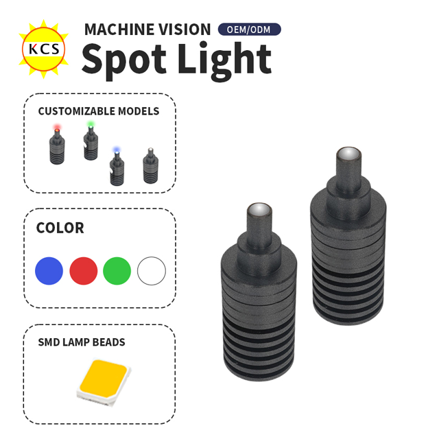
Technical Profiling: The Industrial LED Spot Light for Vision
Structurally, these units serve as concentrated, highly directional emitters. They often function similarly to a collimated point light when paired with specialized internal optics. Integrators design them to flood a precisely targeted Field of View (FOV) from an offset angle.
An industrial LED spot light for vision offers immense optical penetration power. It easily maintains high lux levels at extended working distances. Diffuse ambient lights typically fall off rapidly over physical space. A highly directional source pushes photons deep into the targeted inspection zone.
Shadow casting represents another massive integration advantage. By angling the emitter heavily, engineers purposefully create directional shadows. Darkfield illumination techniques highlight topographical defects perfectly. Minor surface scratches, raised metallic embossing, and subtle physical depth changes suddenly pop out against dark backgrounds. Space flexibility adds significantly to their industrial appeal. You can mount them well outside the immediate camera physical envelope. This keeps the space directly above the production conveyor completely clear of bulky equipment.
However, they carry inherent structural limitations. Shiny or highly specular surfaces run a massive risk of developing harsh "hotspots". Concentrated narrow beams reflect aggressively off polished metals. Furthermore, they demand incredibly precise aiming during installation. You must use robust mechanical fixturing. This ensures the narrow beam remains consistently focused on the exact micro-target area despite heavy machine vibrations.
Technical Profiling: Ring Light Topologies
Ring units consist of densely packed circular arrays of LEDs. Manufacturers mount these circular arrays coaxially around the camera lens body. They deliver photons inward from all azimuthal angles simultaneously.
Shadow eradication stands out as their primary optical strength. The omnidirectional light output flattens complex textures completely. It effectively eliminates harsh directional shadows across the entire FOV. You gain perfectly even illumination on flat objects.
Integration simplicity drastically speeds up the physical deployment process. Many standard models mount directly to the camera lens outer threads. This effectively minimizes the spatial footprint directly above the inspection line. When paired internally with a frosted diffuser, they inspect non-reflective surfaces beautifully. Matte plastics, paper labels, and densely populated printed circuit boards (PCBs) illuminate with perfect uniformity.
Despite these notable benefits, ring units struggle significantly on challenging topographies. They remain highly prone to severe specular optical reflection. Shiny, curved, or polished metallic parts bounce the circular array directly back into the camera lens. This immediately creates a blinding white ring artifact on the digital image. Additionally, their effective working distance remains relatively short compared to intensely directed point sources. You cannot mount them far away without losing critical intensity.
Evaluation Dimensions: Matching Hardware to Target Topography
Working Distance (WD) vs. Field of View (FOV)
Working distance drastically changes how any illumination behaves in physical space. As a general integration rule of thumb, a spot light scales beautifully for extremely long WDs and tight FOVs. High-quality focused optics prevent unwanted beam spread over large physical gaps. Conversely, ring arrays lose uniformity exponentially as you pull them backward. The physics of the inverse square law diminishes their diffuse intensity rapidly over air.
Surface Specularity and Geometry
The physical geometry of the inspected part dictates light reflection behavior. We call this vital evaluation the glare test. Flat, completely matte surfaces tolerate overhead ring topologies perfectly well. However, highly reflective components require a fundamentally different optical approach. Curved metal cylinders and shiny ball bearings act exactly like convex mirrors. They will reflect the precise geometric shape of your light source directly into the sensor. To inspect these complex parts properly, you need steeply angled beams or specialized low-angle off-axis illumination. Directional darkfield techniques push the blinding glare safely away from the CMOS sensor.
Mounting Footprint and Payload Limits
Strict physical space constraints often force an automation engineer's hand during design. You must evaluate the total payload weight on the robotic arm for dynamic guided applications. Fixed-station structural rigging offers slightly more flexibility. Coaxial circular lights save significant lateral space inside tight machine enclosures. They hug the camera body tightly, creating a single compact cylindrical profile. Offset directional beams require bulky external mounting brackets. They consume highly valuable lateral volume inside the primary machine enclosure.
Implementation Realities & Integration Risks
Proper system integration goes far beyond simple optical theory. Harsh physical environment factors quickly degrade illumination performance if left ignored.
Thermal management directly impacts total LED lifespan and color consistency. High-intensity light output generates significant internal heat. This proves especially true for units operating continuously. Unmanaged thermal loads lead to rapid LED component degradation. Micro-spectrum shifts and gradual intensity drops ruin your digital inspection baseline over months. Always evaluate thoroughly if your specific setup requires active external heat sinking or passive thermal mounting blocks.
Strobing offers a brilliant optical way to freeze motion on high-speed manufacturing lines. Overdriving a machine vision source in pulsed strobe mode yields incredibly intense brief bursts. However, hardware controller synchronization must operate flawlessly. Your external illumination trigger must perfectly match the internal camera exposure window. Microsecond timing delays cause dark images, blurred edges, and immediate false rejects.
Bracket creep introduces silent, progressive failures into stable systems. High-vibration heavy manufacturing floors shake loose poorly secured metal mounts. Offset localized point sources remain highly vulnerable to physical drifting. A tiny fractional angular shift completely ruins the established contrast profile. Rigidly lens-mounted circular units suffer far less from this severe vibration vulnerability due to their low center of gravity.
Shortlisting Logic: Next-Step Actions for Integrators
You need a rigorous, structured method to choose correctly between these two core technologies. Use the following hardware decision matrix to narrow down your initial options quickly.
Target & Environment Requirement | Optimal Hardware Choice | Primary Engineering Reason |
|---|---|---|
Flat or matte surface profile | Ring Light | Provides perfectly even, shadow-free illumination across the target. |
Extremely long working distance (WD) | Spot Source | Concentrated directional optics maintain high lux levels over distances. |
Depth extraction (embossing or scratches) | Spot Source | Angled mounting intentionally casts distinct shadows for edge contrast. |
Strictly limited lateral machine space | Ring Light | Mounts directly to the lens, keeping the physical footprint narrow. |
Highly reflective curved metallic objects | Spot Source (Off-axis) | Redirects severe specular reflection away from the camera lens. |
Reviewing this simple matrix serves only as the very first step. You must move quickly into the physical proof-of-concept phase. Integrators should always aggressively request evaluation units from optical vendors. Test them thoroughly using actual production samples directly on your lab bench. Test both absolute pass and extreme fail edge-cases. Hardware prototyping proves the only truly verifiable way to validate your final setup before locking down the Bill of Materials (BOM).
Common advanced integration steps include:
Defining the absolute maximum allowable physical working distance.
Identifying the single smallest micrometer defect the digital camera needs to catch.
Testing multiple steep incidence angles to aggressively maximize background contrast.
Documenting the exact microsecond exposure times needed to freeze conveyor motion.
Simulating the worst-case ambient factory floor lighting to ensure robust optical isolation.
Conclusion
Neither the localized directional beam nor the coaxial ring proves universally superior. Their ultimate efficacy remains strictly tethered to the physical geometry and surface reflectivity of the inspection target. Hardware illumination choices strictly dictate your downstream software's ability to succeed. Successful industrial machine vision deployments rely entirely on rigorous empirical testing. You absolutely cannot rely strictly on basic datasheet assumptions. Real-world physical parts behave unpredictably under intense artificial illumination. We strongly recommend taking clear actionable steps today. Request a physical lighting evaluation kit from your trusted supplier. Submit a complex sample part for a dedicated lab test. Consult directly with an experienced optical engineer to strictly validate your specific use case. Securing the exact right hardware geometry permanently eliminates false rejects and deeply stabilizes your automated inspection lines.
FAQ
Q: Can a spot light act as a collimated point light?
A: Yes, but only when paired with specific optical lenses. Standard directional emitters naturally diverge over distance. To truly collimate the beam, you must use precision optics that align the light rays in parallel. This configuration prevents beam spread, ensuring intense, focused illumination across extremely long working distances.
Q: How do I eliminate glare when using a ring light on metallic parts?
A: Integrating cross-polarizers serves as the most effective immediate fix. Place a polarizing film directly over the LEDs and a corresponding optical filter on the camera lens. If severe glare persists on highly curved metals, you should transition to cloudy-day or dome illumination to fully diffuse the source.
Q: Is an industrial LED spot light for vision safe for continuous operation?
A: It is generally safe, provided you manage internal thermal limits carefully. Continuous operation generates significant heat, which can degrade LEDs over time. Using dedicated heat sinks extends their lifespan. Alternatively, running the unit in an overdriven strobe mode reduces the thermal load while maximizing brief inspection intensity.
Q: What is the maximum effective working distance for a standard ring light?
A: Most standard ring arrays operate effectively under 300mm. Beyond this physical range, the inverse square law causes the diffuse illumination to degrade rapidly. Optical uniformity drops, and ambient light interference increases. For longer distances, integrators typically transition to high-intensity directional point sources.


