

Why Do Output Voltage and Current Matter in a Light Source Controller?
Views: 0 Author: Site Editor Publish Time: 2026-08-12 Origin: Site


Specifying output voltage and current is never just a basic electrical checkbox. In reality, it represents a critical fail-point across machine vision and industrial lighting applications. Mismatched output parameters remain the leading cause of inconsistent illumination on modern factory floors. They trigger premature LED degradation, introduce complex thermal failures, and ultimately cause false rejects during automated defect inspection. Ignoring these electrical nuances will severely compromise your optical inspection accuracy.
Selecting a reliable Light Source Controller requires moving far beyond nominal datasheet values. You must fully understand how specific drive methods dictate hardware compatibility. We will explore how voltage and current specifications directly influence system stability. By mastering these output parameters, you ensure consistent brightness, optimize image contrast, and drastically prolong the lifespan of your critical optical components.
Key Takeaways
Matching output current precisely dictates illumination stability, directly impacting camera exposure and image processing accuracy.
The choice between Constant Current (CC) and Constant Voltage (CV) controllers depends entirely on the internal circuitry of the connected illuminator.
Advanced lighting techniques, such as strobing high-density fixtures like a coaxial light, require strict adherence to peak current and voltage limits to prevent thermal damage.
Safety compliance (e.g., Class I/II, Class 2) and power stability are intrinsically linked to how a controller manages its output loads.
The Technical and Operational Impact of Output Parameters
Inconsistent light output directly creates measurable business losses. Machine vision systems rely entirely on stable illumination to capture high-contrast images. When output parameters fluctuate, your cameras capture varying exposure levels. This inconsistency forces defect detection algorithms to yield higher false positive rates. Entire production lines suffer unexpected downtime while technicians struggle to recalibrate software thresholds. In reality, the root cause often traces back to poorly matched electrical parameters.
The controller must consistently overcome the LED array's forward voltage (Vf). Every diode requires a specific minimum voltage to begin conducting electricity and emitting light. If the controller fails to meet this threshold, the fixture simply will not turn on. Industrial environments introduce another layer of complexity known as voltage droop. Long cable runs across factory floors naturally resist electrical flow. A controller outputting exactly 24V at its terminals might only deliver 22V by the time it reaches a distant light fixture. You must account for this resistance and select controllers capable of compensating for line losses.
Current requirements dictate both brightness and heat generation. Machine vision lighting operates on a fundamental physics principle: a linear relationship exists between forward current and luminous flux. Supplying more current directly produces more light. However, you cannot scale this infinitely. LED efficiency drops as current increases, converting excess energy directly into heat rather than usable light.
This introduces a harsh thermal reality. Supplying excessive current without proper thermal management creates a dangerous condition known as thermal runaway. As temperatures rise, the forward voltage drops, which pulls even more current from unregulated sources. This destructive cycle drastically reduces the lifespan of the lighting hardware. Precision control over these output parameters prevents premature equipment failure.
Constant Current (CC) vs. Constant Voltage (CV): Selecting the Right Drive Architecture
Understanding your illuminator's internal circuitry is mandatory before selecting a power source. We categorize modern control solutions into two primary operational modes: Constant Voltage (CV) and Constant Current (CC). You cannot mix these architectures without risking severe equipment damage. Each mode addresses fundamentally different hardware designs.
When to Specify Constant Voltage (CV)
Constant Voltage controllers deliver a fixed voltage level, typically 12V or 24V, regardless of the connected load. You specify CV architectures when your illuminator features built-in current-limiting resistors. Manufacturers often design flexible LED strips and basic ring lights this way. The internal resistors handle the task of restricting current flow to the individual diodes.
Pros: You can easily scale multiple lights on a single channel. Connecting fixtures in parallel remains simple. Installation requires less technical matching.
Cons: Brightness uniformity suffers. As resistors heat up, their resistance changes, leading to subtle shifts in current. This causes slight flickering or intensity variations across the fixture.
When to Specify Constant Current (CC)
Constant Current controllers dynamically adjust their output voltage to maintain a strictly regulated current flow. You specify CC architectures for direct-drive LED arrays. These fixtures lack internal resistors and connect directly to the power source. High-end machine vision applications almost exclusively rely on direct-drive setups to achieve maximum optical performance.
Pros: Ensures absolute brightness stability regardless of ambient temperature fluctuations. It delivers the precise microsecond responsiveness required for high-speed imaging.
Cons: Requires strict matching to the specific LED array's maximum rating. Supplying incorrect current instantly damages the hardware. You generally cannot string multiple distinct fixtures in parallel on a single channel.
To navigate these choices, engineers use a practical evaluation framework. Always check the illuminator's datasheet first. If the document lists a specific milliampere (mA) rating and explicitly mentions a lack of internal resistors, CC is mandatory. If the datasheet highlights a fixed input voltage and provides a wide wattage range, you need a CV source.
Feature | Constant Current (CC) | Constant Voltage (CV) |
|---|---|---|
Primary Application | High-precision machine vision arrays | Flexible strips, basic indicator lights |
Output Regulation | Dynamic voltage, fixed current | Fixed voltage, dynamic current |
Thermal Stability | Excellent (Prevents thermal runaway) | Moderate (Relies on internal resistors) |
Hardware Requirement | Direct-drive LEDs without resistors | LEDs grouped with internal resistors |
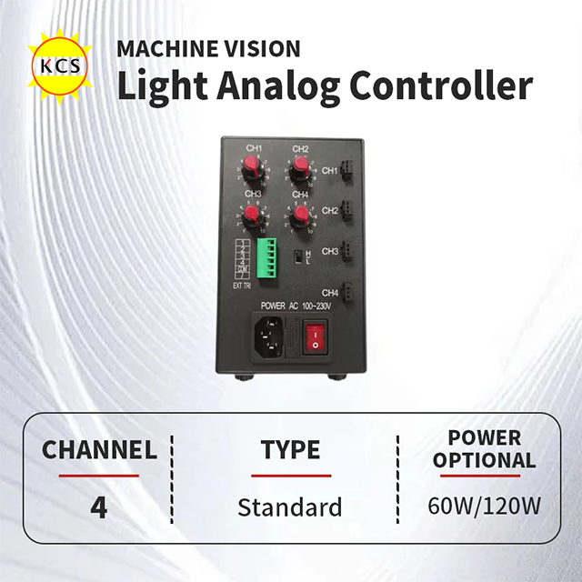
Evaluating Output Specs for Specific Fixtures: The Coaxial Light Use Case
Applying this knowledge to specialized hardware reveals why precise output matching matters. We frequently use a Coaxial Light as the primary example of strict electrical dependency. Manufacturers design these fixtures to illuminate highly reflective, specular, or severely uneven surfaces. They are indispensable for inspecting mirrored PCBs, polished metal bearings, and glass wafers.
Strict hardware constraints govern their operation. Coaxial setups utilize an internal half-mirror angled at 45 degrees. To push enough light through this beam-splitting mirror and onto the target, they employ exceptionally high-density LED arrays. Because the internal LEDs are densely packed into a small metallic housing, they exhibit high sensitivity to current overloads. Poorly regulated power causes localized hot spots, shifting the color temperature and ruining inspection consistency.
Matching feature-to-outcome requires precision electronics. Operators face the constant challenge of eliminating hot-spot glare from the reflective target. Using a controller with micro-stepping current adjustment solves this problem. This feature allows technicians to dial in the exact brightness needed to pierce the optical setup without risking thermal damage. You gain granular control over the luminous flux, optimizing the camera's dynamic range.
Successful system integration hinges on careful electrical planning. You must highlight the necessity of matching the controller's voltage range to the specific string configuration of the fixture. High-density fixtures often wire numerous LEDs in series, pushing the total forward voltage requirement significantly higher than standard units. If your power source cannot swing its voltage high enough while maintaining the constant current, the coaxial fixture will simply fail to illuminate.
Overdriving and Strobe Control: Handling Peak Voltage and Current
Modern manufacturing rarely stands still. Continuous lighting causes severe motion blur on high-speed inspection lines. Cameras tracking fast-moving targets require extremely short exposure times, often measured in microseconds. Capturing sharp images under these constraints demands advanced evaluation dimensions. You must deliver massive amounts of light in a tiny fraction of a second.
Engineers achieve this by differentiating between a controller’s continuous current rating and its strobe capacity. Overdriving involves intentionally pushing current well beyond the LED's standard continuous rating. A fixture rated for 1A continuously might easily survive a 3A burst. However, this demands sophisticated electronics capable of switching massive loads almost instantaneously.
The physics of overdriving dictate strict operational boundaries. Pushing 2x or 3x the nominal current is safe only if the controller precisely limits the pulse width and the duty cycle. The pulse width represents the actual time the light remains on. The duty cycle represents the ratio of "on" time to "off" time. Exceeding a 10% duty cycle while pushing maximum peak current will melt the diode wire bonds instantly. The off-cycle provides the crucial thermal relaxation time necessary for the fixture to cool.
Proactive risk mitigation separates robust integrations from catastrophic failures. We strongly advise buyers to verify specific hardware safeguards before purchasing. Look for automatic pulse width limiters built directly into the silicon. Software controls remain vulnerable to system crashes. If a software glitch leaves an overdriven output stuck in the "on" position, it will instantly destroy the connected fixture. Hardware-level timeouts act as an absolute fail-safe, cutting power regardless of network commands.
Implementation Risks, Stability, and Compliance Standard
Procuring industrial electronics requires a thorough understanding of authoritative compliance lenses. Output voltage and current directly impact international safety classifications. You must differentiate between UL Class 2 power limits and Class I/II isolation requirements. A UL Class 2 designation strictly limits the output to 100 watts and 5 amps under any condition. This prevents fire hazards and shock risks in the event of a short circuit. If your lighting system requires massive overdrive bursts exceeding these limits, you step out of Class 2 territory. This shift drastically changes your cabling, conduit, and enclosure requirements.
Electrical noise and EMI present hidden implementation risks. Cheaply designed controllers often struggle to regulate output current smoothly. They rely on low-frequency switching mechanisms that introduce severe electrical noise into the environment. This poorly managed power radiates electromagnetic interference across the factory floor. EMI easily couples into nearby sensor lines or GigE camera cables. When this happens, cameras drop frames, trigger signals jitter, and the entire vision system becomes unreliable.
Engineers frequently fall into a dangerous implementation pitfall: the assumed capacity trap. You read a datasheet stating a controller is rated for "24V / 2A" across four channels. It feels safe to assume you can connect four 2A lights simultaneously. However, many budget devices cannot sustain max current across all channels simultaneously without adequate heat sinking. They rely on power supply derating curves. Operating at max capacity inside a hot electrical cabinet causes internal components to overheat, leading to sudden voltage drops and inspection failures. Always calculate the total simultaneous load and verify the ambient temperature rating.
Conclusion
Securing a stable machine vision environment begins with rigorous specification matching. Adopting a strict shortlisting logic prevents costly hardware failures and minimizes inspection downtime.
Identify the illuminator's specific drive type by consulting the datasheet to choose between CC and CV architectures.
Calculate the total forward voltage required for the string and determine the exact operating current needed for optimal brightness.
Determine if your inspection speeds require strobing, and verify hardware-level fail-safes for overdriving routines.
Verify ambient temperature limits to avoid power derating issues inside sealed factory enclosures.
Take immediate action to audit your current lighting failure rates. Cross-reference burned-out fixtures against their connected power sources. If you notice a high turnover of specific lights, consult with a technical sales engineer to audit your controller-to-light pairing matrix. Correcting these mismatches delivers immediate improvements to your production line yields.
FAQ
Q: What happens if a light source controller's output voltage is slightly higher than the LED's rating?
A: In CV systems, it leads to exponentially higher current and rapid burnout if no resistors are present. In CC systems, the controller automatically adjusts voltage to maintain the target current, up to its maximum limit, ensuring safe operation.
Q: Can I connect a constant voltage coaxial light to a constant current controller?
A: No, doing this causes severe electrical instability, erratic flickering, or immediate component failure. Drive types must match precisely. CC controllers cannot accurately regulate current if they are fighting against internal voltage-dropping resistors.
Q: Why does my LED light flicker even though the controller output matches the datasheet?
A: Flickering usually indicates a low-frequency PWM dimming method conflicting directly with the camera's shutter speed. It can also occur if the power supply hits its maximum current threshold and repeatedly drops out under load.


