

What Is a Light Source Controller and How Does It Work in Machine Vision?
Views: 0 Author: Site Editor Publish Time: 2026-08-12 Origin: Site


In machine vision, image processing algorithms are only as reliable as the image captured. Fluctuating illumination quickly leads to false rejects of good parts or false accepts of critical defects. A simple power supply cannot solve these complex optical inconsistencies. A true Light Source Controller acts as a central synchronization hub. It seamlessly bridges the camera, the inspection software, and the LED hardware to guarantee absolute photonic consistency. By precisely managing power delivery, it removes the guesswork from factory floor imaging. Before evaluating specific models or topologies, you must understand the technical mechanisms at play. We will explore what separates basic power delivery from precision machine vision lighting control. You will learn how these devices regulate current, synchronize microsecond triggers, and extend hardware lifespans.
Key Takeaways
Consistent Imaging: Controllers regulate current and voltage to eliminate flicker, ensuring absolute brightness consistency across millions of inspection cycles.
Hardware Synchronization: They enable microsecond-level synchronization between the camera shutter and the LED pulse, critical for high-speed, blur-free inspection.
Thermal & Lifespan Management: By precisely overdriving LEDs only during the camera exposure window, controllers maximize lumen output while mitigating thermal degradation.
Application-Specific Selection: Choosing between an Analog Controller and a digital strobe unit depends entirely on line speed, budget, and integration complexity.
The Mechanics: How a Light Source Controller Actually Works
Light emitting diodes operate strictly as current-driven devices. When input power fluctuates, a basic voltage supply fails to keep illumination steady. Furthermore, as an LED heats up during operation, its forward voltage naturally changes. The controller maintains a constant current despite these rapid shifts. It continuously monitors the output and adjusts the delivery dynamically. This strict regulation prevents dangerous current spikes and eliminates frustrating camera flicker.
Triggering relies on a highly precise signal sequence. We call this interaction the hardware handshake. The process flows logically across the inspection cell:
A PLC or photo-eye sensor detects an approaching part on the fast-moving conveyor.
The sensor immediately sends a trigger signal to the control unit.
The controller fires the LED array at the exact specified intensity.
Simultaneously, the controller triggers the camera shutter to capture the frame.
Consumer electronics tolerate broad millisecond delays. Machine vision hardware demands absolute microsecond latency. If a trigger arrives even one millisecond late, a fast-moving part easily leaves the inspection frame. This delay causes missed inspections and rejected batches.
Controllers manipulate light intensity using two primary methods. Some use continuous output regulation. They adjust the constant direct current level flowing to the light. Others utilize high-frequency Pulse Width Modulation (PWM). PWM pulses the LED on and off at rates exceeding tens of thousands of times per second. This rapid switching allows you to dim the light effectively. Crucially, PWM dimming does not shift the underlying color temperature of the diodes.
Direct Power vs. Dedicated Control: The ROI of Precision
Engineers often attempt to cut corners during initial system integration. They wire machine vision LEDs directly to a standard 24V DIN-rail power supply. We call this the direct power fallacy. Standard supplies regulate voltage, not current. They offer zero synchronization capabilities for automated environments.
Unregulated power quickly leads to thermal runaway. When LEDs heat up, their internal electrical resistance drops. They draw more current from a basic power supply, creating even more destructive heat. This vicious cycle causes severe optical wavelength shifts. A red LED might shift toward orange as it burns hot. This shift destroys the contrast needed by the vision algorithm. Eventually, this unchecked heat causes premature hardware failure.
Direct wiring also makes ambient light overpowering impossible. Factory environments contain bright overhead lighting and sunlight spilling through large windows. To isolate the inspection, you must overdrive the LED array. Overdriving involves strobing an LED at three to ten times its nominal current rating. This intense burst lasts only a fraction of a millisecond. It freezes fast motion completely. It also drowns out all ambient factory light entirely. A dedicated controller safely executes this overdrive sequence without melting the diodes.
Investing in precision control yields measurable business outcomes. You avoid costly false failures caused by varying image contrast. You extend the operational lifespan of expensive LED arrays significantly. Most importantly, you drastically reduce unexpected machine downtime across the production facility.
Solution Categories: Analog Controllers vs. Digital/Strobe Controllers
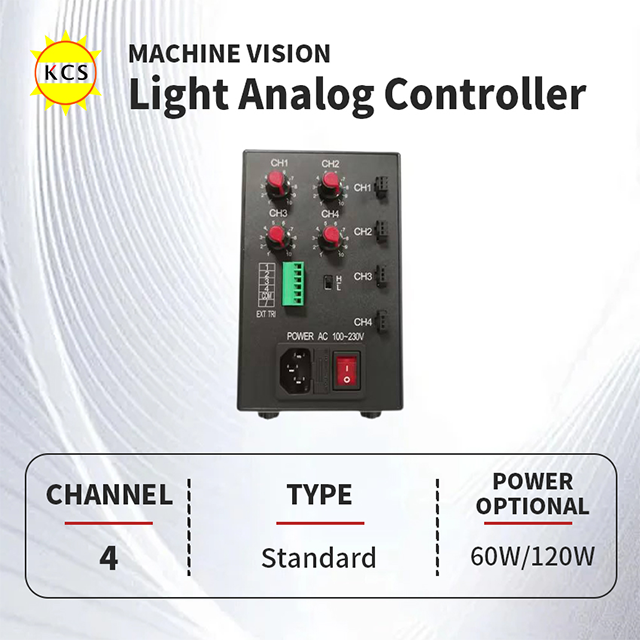
The Analog Controller (Continuous Control)
An Analog Controller allows manual intensity adjustment. Operators use physical potentiometers located directly on the front panel. Alternatively, they send simple external 0–5V or 0–10V analog signals from a PLC to control brightness.
These units fit perfectly into specific operational environments. We recommend them heavily for continuous web inspections or low-speed automation cells. They excel in applications utilizing industrial cameras equipped with rolling shutters. They also provide a reliable, cost-effective solution for highly budget-constrained projects.
However, analog models carry inherent system limitations. They lack precise microsecond strobe capabilities needed for freezing ultra-fast motion. Manual dials introduce significant human error risks. Operators might accidentally bump the knobs on a busy factory floor. This simple mistake ruins the illumination calibration instantly.
Digital and Strobe Controllers
Digital controllers utilize advanced microprocessors to manage complex illumination tasks. They replace physical knobs with Ethernet, RS232, or GigE Vision communication interfaces. This robust connectivity enables highly programmable, recipe-driven adjustments directly from a central network.
These devices dominate high-speed web inspection and intricate multi-camera setups. They remain essential for applications requiring intense LED overdriving. If your environment demands remote configuration to switch between product batches instantly, digital control is absolutely necessary.
The primary limitation is the higher initial upfront cost. Furthermore, engineering teams must allocate dedicated time for software programming and network integration.
Key Evaluation Dimensions for Shortlisting a Controller
Selecting the correct unit requires matching technical specifications to your exact application. You must evaluate several critical dimensions before making a purchase decision.
First, assess your output channel and scalability requirements. Controllers typically feature one, two, four, or eight independent channels. You must decide if multiple lights need grouping together. Sometimes, a single complex inspection sequence requires triggering lights independently from one central command unit.
Next, match the maximum output current and overdrive capability precisely. Check the LED head's data sheet carefully. If the controller outputs too little current, you underpower the light severely. If it pushes too much continuous current, you quickly fry the expensive LED array.
Trigger latency and jitter represent critical timing metrics for automation. Latency is the delay between receiving a trigger and the light actually firing. Jitter is the variance in that delay across multiple inspection cycles. For high-speed lines like beverage bottling, jitter must remain strictly in the low microseconds.
Finally, verify communication protocols and compliance standards. Look for seamless integration capabilities matching existing industrial networks like Profinet, EtherCAT, or CC-Link. Always verify CE and RoHS compliance for international factory deployments.
Evaluation Dimension | Standard Requirements | Advanced Requirements |
|---|---|---|
Output Channels | 1 to 2 single-trigger zones | 4 to 8 independent programmable zones |
Trigger Timing | Millisecond response times | Microsecond latency and near-zero jitter |
Power Delivery | Constant continuous current | High-current overdrive pulses |
Networking | Manual knobs or 0-10V analog | GigE, Profinet, EtherCAT integration |
Implementation Realities and Integration Risks
Even the best hardware fails if integrated poorly. Engineers must address the physical realities of the harsh factory floor. Long cable runs between the controller and the light source cause inevitable voltage drops. This electrical resistance alters the pulse shape drastically. It degrades the final light intensity reaching the inspection zone. Always minimize cable lengths wherever physically possible.
Factory environments are notoriously electrically noisy. Heavy machinery creates ground loops and electromagnetic interference. This noise wreaks havoc on sensitive timing signals. You must utilize opto-isolated trigger inputs. Opto-isolation uses internal light to transmit signals, breaking the physical electrical connection entirely. This crucial barrier protects both the controller and the expensive camera from unexpected voltage spikes.
Avoid a "set and forget" mentality regarding system calibration. Maintenance teams eventually replace damaged lights or swap out worn cables. If you use analog dials, document the exact intensity values rigorously. Implement strong recipe management practices across your facility. Proper documentation ensures rapid recovery and prevents hours of frustrating recalibration.
To ensure long-term success, follow these practical integration best practices:
Measure cable voltage drops using an oscilloscope during the initial setup phase.
Shield all communication and trigger cables away from heavy motor drives.
Use dedicated ground wires to eliminate noisy electrical loops effectively.
Record all baseline intensity settings in the central factory maintenance log.
Conclusion
Lighting control operates as a critical variable in the machine vision equation. It should never be an afterthought during system design. Without stable photons, even the most advanced AI algorithms fail to detect defects accurately. Precision control hardware translates directly into higher production yields and fewer false rejections.
Your shortlisting logic should remain practical and straightforward. If your manufacturing process is slow and continuous, a standard analog unit suffices perfectly. However, if you must freeze high-speed motion with absolute repeatability, digital strobe control becomes entirely mandatory.
Take action by auditing your current conveyor line speeds. Calculate your required camera exposure times and maximum allowed trigger latency. Reach out to equipment manufacturers and request evaluation loaner units. Test these devices in your actual factory ambient conditions to validate their performance before committing to a full-scale deployment.
FAQ
Q: Can I use a standard LED driver instead of a machine vision light source controller?
A: No. Standard drivers lack microsecond trigger inputs, exact current stability, and the high-current overdrive necessary for industrial inspection cameras.
Q: What is the difference between PWM and analog dimming?
A: Analog dimming lowers the constant current to dim the light, which can shift the LED's color temperature. PWM rapidly flashes the LED at full current; the ratio of "on" to "off" time dictates perceived brightness without altering color, though it requires careful matching with camera exposure times to avoid banding.
Q: How do I match my LED light to the right controller?
A: Check the LED's maximum continuous current rating, peak strobe current rating, and connector pinout, then select a controller that supports those precise electrical thresholds and communication protocols.


