

Please Choose Your Language
Views: 0 Author: Site Editor Publish Time: 2026-09-30 Origin: Site


A machine vision system is only as capable as its weakest optical link. Pairing a premium sensor with an inadequate lens results in artificial bottlenecks, false rejects, and degraded data. We often see automation facilities invest heavily in high-end cameras. They then compromise their inspection results by installing inferior optics. Selecting an industrial lens requires balancing mathematical optical constraints against the physical realities of your deployment environment. You must account for sensor size, pixel pitch, and working distance accurately. Ignoring these variables causes edge data loss and introduces mechanical failures on the production line.
This guide breaks down the objective criteria for evaluating and shortlisting optical components. You will learn how to match lenses to sensors and navigate complex optical trade-offs. We will also cover how to protect equipment from harsh factory conditions. Ultimately, we will ensure your vision system meets its designated success metrics without over-specifying unnecessary features.
Sensor Coverage is Non-Negotiable: The lens image circle must equal or exceed the sensor format of your camera to prevent mechanical vignetting.
Resolution Must Match Pixel Pitch: A high-megapixel sensor requires a lens with a corresponding Modulation Transfer Function (MTF) to genuinely resolve fine details.
Distortion Impacts Measurement: Applications requiring precise dimensional gaging demand low-distortion optics (often <0.1%), whereas standard defect detection can tolerate higher distortion limits.
Mechanical Stability Matters: Ruggedized housings and locking screws are critical for maintaining focal integrity in high-vibration manufacturing environments.
Establishing what the vision system fundamentally tries to achieve is your first operational step. You must define what constitutes a successful inspection. The acceptable margin of error dictates the optical tolerance and overall system complexity. We strongly recommend setting clear parameters before reviewing lens catalogs.
Follow these steps to establish your baseline criteria:
Identify the core inspection objective for the specific production line.
Determine the smallest defect or feature size you must reliably detect.
Measure the physical space limits around the inspection zone.
Vision applications generally fall into two categories. Each requires a distinct optical approach. Metrology and gaging demand absolute dimensional accuracy. These applications require strict minimization of optical distortion. Engineers often utilize telecentric lenses here. Telecentric optics maintain constant magnification regardless of the object's distance from the lens. This geometry ensures highly accurate edge detection across the entire field.
Conversely, presence or absence detection tasks are more forgiving. You can utilize standard entocentric lenses for these applications. Slight field curvature or minor distortion does not typically impact a simple pass/fail decision. You can simplify the optical design when absolute measurement precision is unnecessary.
You must calculate your baseline optical triangle early in the design phase. The Field of View (FOV) is the physical area the camera needs to see. The Working Distance (WD) is the space between the front of the lens and your target object. Physical constraints on the production line dictate permissible focal lengths. Clearance above moving conveyors often restricts your maximum WD. Robotic arm payloads similarly limit camera placement. You must calculate the required focal length based on these rigid physical boundaries.
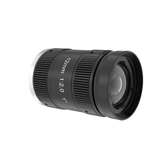
Optical compatibility extends beyond physical thread sizes. You must align the mathematical capabilities of the lens with the specific sensor architecture.
A direct relationship exists between the camera sensor format and the projected image circle of the lens. Common sensor formats include 1/2", 2/3", and 1.1" sizes. The lens captures light and projects it backward as a circular image. This circle must completely cover the rectangular sensor of your industrial area scan camera.
Risk Warning: Undersizing the lens image circle produces severe consequences. The corners of the sensor will receive no light. This creates dark, curved borders known as vignetting. You will permanently lose inspection data at the edges of the frame. Always verify the lens format equals or exceeds the sensor size.
Megapixel counts only tell half the story. A sensor dense with pixels cannot overcome a blurry optical projection. You must evaluate how well an industrial lens for area scan camera resolves fine details. Industry standards measure this resolving power in line pairs per millimeter (lp/mm).
We rely on Modulation Transfer Function (MTF) charts for accurate evaluation. MTF charts verify edge-to-edge sharpness. Do not rely solely on center-only resolution specifications. Center sharpness often degrades rapidly toward the outer image field. MTF curves objectively plot contrast retention against spatial frequency.
Modern sensors routinely feature sub-3-micron pixel sizes. These tiny pixels demand exceptionally sharp optics. Justifying the investment in a high-resolution industrial camera lens becomes essential here. Standard definition lenses will smear incoming light across multiple pixels. This completely negates the resolving advantage of your high-megapixel sensor.
Physical integration requires strict adherence to industry mounting standards. Each mount type features a specific Flange Focal Distance (FFD). The FFD is the precise measurement from the mounting flange to the sensor plane.
The machine vision industry relies on a few core thread standards. The C-mount machine vision lens serves as the dominant industry standard for sensors up to 4/3". It balances a compact physical size with highly reliable threading. C-mounts feature a 1-inch diameter thread and an FFD of 17.526 mm.
Other applications utilize CS-mount, S-mount (M12), or F-mount interfaces. S-mounts dominate board-level and highly compact cameras. Large line-scan sensors typically require the robust F-mount. You must exercise extreme caution regarding spacer rings. Using incorrect spacer rings alters the FFD. This misalignment prevents the camera from achieving proper infinity focus.
Standard Machine Vision Lens Mounts Comparison
Mount Type | Thread Specification | Flange Focal Distance (FFD) | Typical Sensor Size Application |
|---|---|---|---|
C-Mount | 1" x 32 TPI | 17.526 mm | Up to 4/3" sensors |
CS-Mount | 1" x 32 TPI | 12.500 mm | 1/3" to 1/2" sensors |
S-Mount (M12) | M12 x 0.5 mm | Variable (No fixed standard) | Compact/Board-level sensors |
F-Mount | Bayonet style | 46.500 mm | Large format / Line scan |
You must rigorously evaluate the physical footprint of the lens. Space constraints dictate optical designs in enclosed inspection stations. Weight becomes highly critical in dynamic applications. Robotic arm end-effectors carry the vision system through rapid movements. High lens mass increases the mechanical inertia of the arm. This prolonged motion settling time severely reduces total machine throughput.
Optical engineering requires constant compromise. Adjusting one parameter inevitably alters another. You must navigate these physical trade-offs carefully to optimize system performance.
The lens aperture dictates light gathering and focus depth. We evaluate these adjustments using a strict assumption checklist:
Faster lenses (e.g., f/1.4 or f/2.0) admit significant light.
This light allows for much shorter exposure times.
Shorter exposure times reduce motion blur on fast conveyors.
However, wide apertures severely restrict your Depth of Field (DoF).
A restricted DoF means tall objects will blur at their top edges. You must balance exposure speed against focus depth.
Engineers often attempt to increase DoF by stopping down the aperture. Adjusting the iris to f/16 or f/22 creates a deep focal range. However, this introduces the physics of diffraction. Light waves bend and scatter as they pass through tiny iris openings. This scattering physically blurs the image.
High-resolution sensors suffer greatly from diffraction. The scattered light spots—known as Airy disks—overlap tiny pixels. This completely degrades image sharpness. You must identify the optical "sweet spot" for your setup. This maximum performance zone typically resides between f/4 and f/8.
We frequently utilize external lighting to solve aperture dilemmas. Investing in high-intensity strobe lighting fundamentally changes the optical equation. Powerful strobes flood the target area with photons instantly. This illumination alleviates the need for expensive, wide-aperture lenses. You can comfortably set your lens to its f/5.6 sweet spot. The strobe freezes motion effectively while the mid-range aperture guarantees optimal sharpness and adequate DoF.
Laboratory optical performance means nothing if the lens fails on the factory floor. Industrial environments routinely destroy standard consumer optics. You must evaluate environmental durability rigorously before deployment.
Standard photography lenses fail rapidly in factory environments. Internal motors, plastic gears, and loose elements shift under continuous mechanical vibration. You must evaluate ruggedized lenses for industrial deployments. Rugged lenses feature glued internal glass elements. They also utilize heavy-duty locking thumb screws. These screws permanently secure the focus and iris rings against heavy machine shock.
Industrial facilities frequently experience extreme temperature fluctuations. Cold morning startups transition to intense afternoon heat. These thermal shifts physically alter the refractive index of optical glass. Furthermore, aluminum lens housings expand and contract. This expansion shifts the mechanical focal plane. Focus stability requires thermally compensated lens designs if your environment lacks climate control.
Many inspections occur in dirty or wet environments. You must assess the need for Ingress Protection (IP). Dusty facilities require sealed optics to prevent internal particulate buildup. Food and beverage inspections involve aggressive chemical washdowns. These environments often demand IP67 or IP69K lens enclosures. Protective barrel tubes shield the sensitive glass and threading from corrosive cleaning agents.
Base your initial lens selection on a strict calculation of FOV, Working Distance, and Sensor Size. These physical parameters immediately narrow your viable options. Next, ensure the resolving power matches your pixel pitch. This prevents artificial bottlenecks in data quality.
Always validate your selection thoroughly. Request MTF charts specifically modeled for the working distance of your application. Theoretical performance at infinity focus rarely matches macro-level factory inspection performance. Never assume general specifications apply to your exact setup.
Finally, we recommend conducting a physical proof-of-concept (PoC). Test the optics using calibrated resolution charts on your actual production line. Secure these real-world validation metrics before finalizing procurement for multi-line rollouts.
A: This is typically optical vignetting, occurring when the lens's image circle is smaller than the camera's sensor size, or mechanical vignetting caused by an overly thick lens mount adapter.
A: While technically possible with adapters, standard consumer lenses lack locking screws for vibration resistance, often have varying focal planes (focus breathing), and are not optimized for fixed working distance durability.
A: Both share a 1-inch, 32 TPI thread, but the flange focal distance differs (17.526 mm for C-mount vs. 12.5 mm for CS-mount). A C-mount lens can fit a CS-mount camera with a 5mm spacer ring, but a CS-mount lens cannot be used on a C-mount camera without preventing infinity focus.


