

How to Choose the Right Light Source Controller for a Machine Vision System?
Views: 0 Author: Site Editor Publish Time: 2026-08-12 Origin: Site


Machine vision systems demand absolute precision during every inspection cycle. The most expensive high-end camera becomes completely useless if your illumination varies by even a few percentage points between frames. Many facilities overlook this critical variable. You cannot treat a Light Source Controller merely as a basic power supply. It actually operates as the central timing and stability mechanism for your entire setup. This specific hardware prevents false rejects and eliminates frustrating inspection bottlenecks.
Inconsistent factory lighting ruins image data capture and disrupts automated sorting. This guide cuts through complex spec-sheet noise. We provide a practical, engineering-led framework for evaluating these essential devices. We will explore drive methods, synchronization limits, and crucial integration details. You will learn how to select the exact unit required for your specific production lines. Our systematic approach ensures flawless illumination consistency across your manufacturing floor.
Key Takeaways
Synchronization is everything: Trigger latency and microsecond precision dictate the success of high-speed sorting and web inspections.
Drive method matters: Constant current controllers offer superior stability over constant voltage for LED longevity and consistent intensity.
Overdriving requires precision: Strobe controllers must perfectly balance high-intensity bursts with thermal management to prevent LED degradation.
Integration dictates usability: The choice between networked controllers and a local digital display controller depends on the plant’s reliance on PLCs vs. manual floor adjustments.
The Cost of Poor Illumination Control
Poor illumination control directly harms your daily manufacturing output. Unstable lighting causes vision systems to misinterpret edge detection and surface flaws. This instability generates false positives. False positives force your system to reject perfectly good parts. Wasted yield drains operational budgets quickly. Conversely, inconsistent lighting also creates false negatives. These undetected defects escape the facility. They eventually reach your customers and ruin your brand reputation. A highly reliable controller mitigates these exact risks. It locks in lighting variables to guarantee mathematical predictability.
Improper power management also accelerates catastrophic LED aging. Unregulated current forces light heads to run too hot. Heat acts as the primary enemy of LED longevity. Over time, thermal stress causes "intensity droop." This phenomenon means your light grows progressively dimmer throughout a single production shift. A camera calibrated at 8:00 AM will fail inspections by 3:00 PM. High-quality controllers manage thermal loads effectively. They keep brightness perfectly flat across thousands of continuous operating hours.
Timing presents another hidden failure point. Many engineers mistakenly blame the camera frame rate for blurry images. In reality, controller latency often acts as the true bottleneck. High-speed applications demand microsecond responsiveness. If the hardware delays the flash trigger, the product moves out of frame. The camera captures a poorly lit or entirely missed target. Upgrading your camera cannot fix latency issues originating from cheap power supplies.
Core Evaluation Criteria for Light Source Controllers
Constant Current vs. Constant Voltage
Industry professionals strongly prefer constant current configurations for precise machine vision tasks. LEDs operate as current-driven devices. Their brightness scales linearly based on the supplied current. Constant current hardware guarantees absolute linear brightness. It actively prevents thermal runaway. As an LED heats up, its forward voltage drops. A constant voltage supply would push more current into the warming LED. This cycle eventually destroys the diode. Constant current units adjust automatically to maintain safe operational limits.
Legacy constant voltage units still exist in modern factories. You can sometimes use them for low-precision tasks. They work adequately for basic backlight setups. However, they fail in high-speed, demanding inspections.
Drive Method Comparison Chart
Feature | Constant Current | Constant Voltage |
|---|---|---|
Brightness Stability | Excellent (Linear control) | Poor (Fluctuates heavily) |
Thermal Runaway Protection | Built-in active prevention | None |
Best Application | High-speed, strict tolerance | Basic presence/absence tasks |
Trigger Precision and Latency
Trigger precision dictates the success of dynamic captures. We define acceptable jitter margins in mere microseconds. High-speed web inspections move materials incredibly fast. A tiny 10-microsecond delay shifts your inspection window by several millimeters. This spatial shift ruins the capture entirely. Advanced hardware guarantees latency below three microseconds. You must verify these jitter specifications before purchasing. Do not accept vague marketing claims regarding trigger speeds. Demand hard data regarding maximum response delays.
Single vs. Multi-Channel Configurations
Implementation realities dictate your channel requirements. Multi-channel configurations work best for complex inspection stations. Consider a photometric stereo application. You must fire four different directional lights sequentially. A four-channel unit handles this effortlessly. It synchronizes all sequence timings internally. Sequential multi-angle inspections rely on this centralized coordination.
Conversely, distributed single-channel units benefit large machine builders. A massive assembly line might need lights spread across fifty feet. Routing heavy lighting cables back to one multi-channel panel causes voltage drops. Placing single-channel units directly next to each camera solves this problem. It keeps cable runs short and signals clean.
Interface and Usability: Digital Display Controllers
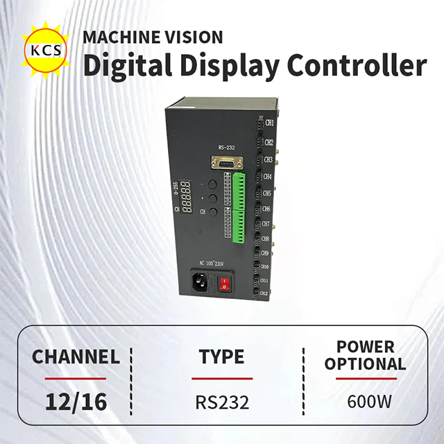
Integration usability directly impacts daily floor operations. Rapid line changeovers require fast, intuitive adjustments. We highly recommend utilizing a Digital Display Controller for these dynamic environments. Operators frequently need to switch product profiles mid-shift. Software-only interfaces force technicians to connect laptops. This process wastes valuable production time.
A physical digital readout allows instant verification. Floor technicians can view and adjust intensity values instantly. They utilize standardized 0-255 step increments. This precise numerical feedback ensures perfect repeatability. If yesterday's successful run used intensity level 142, operators simply punch in 142 today. They achieve this without accessing the main PLC network. These localized interfaces reduce downtime and minimize operator errors.
Advanced Capabilities: Continuous vs. Strobe Modes (Overdriving)
Continuous Mode
Continuous mode supplies uninterrupted power to your lighting array. You should use this mode for stationary inspections. It also works perfectly for low-speed indexing applications. The camera shutter determines the exposure time while the light remains entirely static. This setup simplifies programming significantly.
However, continuous mode introduces major thermal management trade-offs. The LED remains illuminated constantly. It generates immense heat loads. You must provide massive heat sinks. You must also run the LED at lower overall brightness levels. Pushing continuous mode too hard guarantees rapid component failure.
Strobe Mode & Overdriving
Strobe mode pulses the light for tiny fractions of a second. This mode synchronizes perfectly with the camera exposure. It eliminates motion blur entirely. Overdriving represents the pinnacle of strobe technology.
The Physics: Overdriving pulses current at 3x to 10x the nominal rating. It does this for incredibly brief microsecond windows. This massive burst freezes high-speed motion effortlessly.
The Benefit: You generate intense light without buying physically larger arrays.
Risk Mitigation: Specialized controllers protect the light head actively. They enforce strict duty cycle limitations. They apply hard pulse width constraints.
You cannot use a standard power supply for overdriving. The controller must regulate these massive energy bursts. Without internal capacitor protection, a 10x current pulse causes catastrophic LED failure instantly. The hardware acts as a mandatory safety governor for your expensive lighting payload.
System Integration: Networking, PLCs, and Environment
Communication Protocols
Modern automated factories demand seamless data exchange. Standard interfaces like RS232 and standard Ethernet handle basic remote configurations. They allow slow, deliberate parameter changes. However, true industrial environments require faster fieldbuses. Profinet and EtherNet/IP dominate the factory floor. They allow your central PLC to command lighting changes on the fly. GigE Vision protocols synchronize lights directly with specific camera ecosystems. You must match your controller's protocol to your facility's existing network standard.
Form Factor & Thermal Realities
Physical mounting requires careful planning. DIN rail mounting suits crowded electrical cabinets. It saves lateral space. Panel mount designs work better for custom enclosures. Heat dissipation remains a universal challenge. Enclosed electrical cabinets trap heat quickly. Strobe controllers generate significant thermal output during heavy overdriving. You must calculate the internal cabinet temperature. Always specify hardware rated for high ambient heat. Failing to ventilate cabinets leads to random thermal shutdowns.
Compliance & Safety
Industrial safety certifications protect your broader equipment. Always verify CE and RoHS compliance before installation. Electrical isolation requires special attention. Ground loops between the vision system and heavy factory machinery cause erratic behavior. Massive motors induce electrical noise on shared ground lines. Opto-isolated trigger inputs block this noise completely. They keep the sensitive timing circuitry entirely separated from raw factory power. This isolation prevents false triggers and protects the internal microprocessors.
The 4-Step Shortlisting Framework
Choosing the correct hardware requires a systematic approach. Follow this specific framework to narrow down your options quickly. This prevents costly over-speccing and dangerous under-speccing.
Step 1: Define the Capture Speed. Calculate your required camera exposure time. Determine the maximum trigger frequency per second. High frequencies and short exposures make strobe and overdrive mandatory. Slow speeds allow standard continuous mode operation.
Step 2: Calculate Power and Channel Requirements. Review your lighting payload. Match the light head's maximum current ratings to the controller's channel capacity. Never exceed the maximum wattage per channel. Count your distinct light zones to determine the necessary channel count.
Step 3: Determine the Control Hierarchy. Decide which device acts as the master timing clock. The camera can trigger the light. The PLC can trigger both. Sometimes a localized hardware sensor triggers the sequence. Ensure your hardware supports the exact input voltage of your chosen master device.
Step 4: Select the UI/UX. Choose how humans will interact with the system. Remote software configuration works for static lines. Analog potentiometers work for basic setups. A highly repeatable Digital Display Controller works best for rapid, manual line changeovers.
Conclusion
Proper illumination control transforms unpredictable factory environments into highly stable ecosystems. The right hardware turns variable factory lighting into a mathematically predictable variable. You eliminate false rejects and maximize daily yield by locking down your timing and brightness parameters.
Always balance your technical requirements carefully. Over-speccing wastes valuable automation budgets on unused features. Under-speccing ruins inspection reliability and causes constant line stoppages. You must find the precise middle ground.
Take action today by reviewing your application-specific datasheets. Calculate your exact camera frame rates and lighting payloads. Contact an application engineer with your specific trigger setup requirements. They will use this data to provide a perfectly tailored hardware recommendation.
FAQ
Q: What is the difference between a constant current and a constant voltage light source controller?
A: The difference lies in how they deliver power. Current dictates LED brightness directly. Constant current controllers adjust voltage to keep current stable, ensuring perfectly linear brightness. Constant voltage controllers keep voltage static, allowing current to fluctuate as temperatures change. Constant current hardware remains far superior for consistent vision inspections.
Q: Can any light source controller overdrive an LED?
A: No. Standard controllers will instantly destroy an LED if pushed beyond nominal ratings. You require specialized strobe controllers. These units feature built-in duty cycle protections and massive high-current capacitors. They safely manage microsecond power bursts to overdrive LEDs without causing catastrophic thermal degradation.
Q: When should I choose a digital display controller over a software-only interface?
A: We recommend digital display units for dynamic manufacturing floors. Machine operators frequently need to make rapid, localized intensity adjustments during product changeovers. Physical displays allow easily repeatable adjustments (using 0-255 steps) without accessing the main PLC network or connecting a PC to the panel.
Q: How does trigger latency affect my machine vision accuracy?
A: Latency creates critical synchronization mismatches between the camera exposure and the light flash. If the hardware delays the trigger by even a few microseconds, the target moves out of alignment. This results in dark, blurred, or inconsistently lit images, especially at high production speeds.


