

How To Install A Motion Sensor Spot Light?
Views: 0 Author: Site Editor Publish Time: 2026-07-17 Origin: Site


Reliable, motion-triggered illumination dictates the accuracy of surveillance and the efficiency of production lines. Improper installation of triggered lighting systems results in false activations, electrical compliance failures, and inconsistent illumination. In advanced applications, poor placement degrades sensor accuracy, causes costly downtime, and compromises safety. This guide details the technical requirements, placement frameworks, step-by-step electrical integration, and retrofit protocols necessary to successfully install a motion-sensor spot light for commercial, industrial, and automation environments. We will cover the exact wiring configurations, mechanical mounting standards, and environmental sealing techniques required to ensure long-term operational stability.
Safety and Compliance First: All installations must begin with verified power isolation (Lockout/Tagout) and adhere to local electrical codes (e.g., NEC) regarding junction box load, grounding, and weatherproofing.
Application-Specific Placement: Standard security spot lights require a 6- to 10-foot mounting height for optimal PIR (Passive Infrared) sensor range, whereas automation lighting requires precise, application-specific geometry.
Integration Complexity Varies: Wiring ranges from standard 120V/277V line-voltage connections for facility lighting to low-voltage, PLC-triggered configurations for specialized machine vision systems.
Mitigating False Triggers: Proper calibration of sensitivity (range) and time-delay settings is essential to balance operational readiness with energy efficiency and component lifespan.
Retrofit vs. New Install: Evaluating whether to replace an entire legacy fixture or integrate a modular motion sensor into an existing industrial illumination system.
Defining Success Criteria for Motion-Triggered Lighting
Establishing the primary objective of the installation dictates the hardware selection and mounting strategy. You must determine whether the system will serve broad area security, localized safety illumination, or high-speed automated inspection. Each application demands distinct performance metrics. Evaluating lumen output, PIR sensor detection angles, and IP (Ingress Protection) ratings determines survivability in outdoor or washdown environments. A standard security setup typically utilizes detection angles ranging from 180° to 270° to cover wide peripheral zones.
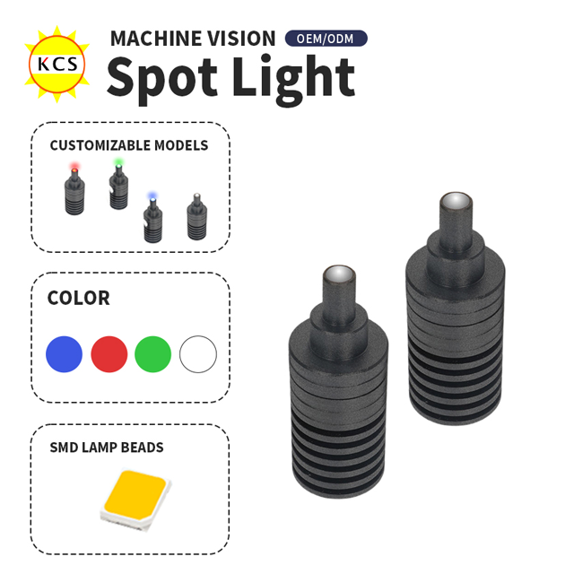
Automation and inspection requirements differ significantly from standard motion lights. When integrating a specialized machine vision light, the success criteria shift toward strobe capabilities, trigger latency, and uniform intensity. An Industrial LED Spot Light For Vision must respond to microsecond triggers without flickering. Assessing ambient temperature, vibration, and exposure to particulates dictates the required housing durability and mounting hardware. You must also decide between an all-in-one motion-activated fixture and installing a standalone motion sensor to control existing non-sensor industrial fixtures.
Application Type | Sensor Requirement | Typical IP Rating | Trigger Latency |
|---|---|---|---|
Facility Security | PIR (180°-270°) | IP65 | Standard (0.5s - 1s) |
Industrial Washdown | Microwave / PIR | IP67 / IP69K | Standard (0.5s - 1s) |
Automated Inspection | PLC / Optical Trigger | IP67 | Microsecond (<1ms) |
System architecture plays a major role in the installation process. Integrated fixtures contain the LED array, driver, and sensor within a single housing. These are faster to install but limit flexibility if one component fails. Modular systems separate the sensor from the luminaire. This allows you to mount the sensor at an optimal detection vantage point while positioning the light source elsewhere for maximum illumination coverage.
Pre-Installation: Evaluating Placement and Sensor Range
Optimal mounting heights and angles directly influence sensor performance. The standard 6- to 10-foot rule applies to facility security installations. Mounting within this vertical range maximizes PIR cross-path detection and eliminates blind spots. Placing the fixture too high reduces the sensor's ability to detect human-sized heat signatures. Placing it too low creates vulnerabilities to tampering and narrows the field of view.
Explaining the geometry of incident light and camera positioning is necessary when installing a Collimated Point Light for high-contrast automation tasks. These specialized units require exact alignment to highlight surface defects or dimensional anomalies. Understanding sensor types and limitations ensures reliable operation. PIR sensors rely on heat differentials, making them ideal for detecting personnel or vehicles. Microwave sensors detect motion reflection and can penetrate non-metallic surfaces. Optical or PLC triggers offer precise control for industrial lines.
Position sensors away from HVAC exhaust vents to prevent thermal false triggers.
Avoid aiming PIR sensors directly at highly reflective surfaces like glass windows or standing water.
Keep the detection zone clear of moving tree branches or high-traffic peripheral roads.
Ensure the sensor has a clear line of sight, free from structural obstructions.
Step-by-Step Installation Process
Phase 1: Preparation, Deinstallation, and Retrofitting
Executing Lockout/Tagout (LOTO) procedures at the breaker panel is non-negotiable. Verifying zero voltage using a calibrated multimeter before interacting with existing wiring prevents severe electrical hazards. Safe deinstallation of legacy fixtures begins with removing existing light bulbs first to prevent accidental breakage during the disassembly process.
Apply LOTO devices to the specific circuit breaker powering the lighting zone.
Test the wires at the junction box with a non-contact voltage tester, followed by a digital multimeter.
Remove the old fixture body and disconnect the wire nuts carefully.
Inspect the existing junction box for structural integrity, corrosion, and volume capacity. Replace compromised boxes immediately.
Phase 2: Physical Mounting and Mechanical Setup
Selecting the appropriate weatherproof, explosion-proof, or dust-ignitionproof junction box depends entirely on the facility environment. Install a universal mounting bracket or mounting strap directly to the junction box. Attach the grounding screw, typically green or bare copper, directly to the metal junction box or mounting strap to ensure electrical safety. This mechanical foundation supports the weight of the fixture and maintains the integrity of the environmental seal.
Phase 3: Electrical Wiring and Integration
Standard line voltage configurations require connecting ground, neutral (white), and hot (black) wires using appropriately sized wire nuts or WAGO connectors. Ensure all connections are secure and tight. When wiring an external motion sensor in-series with a legacy fixture, route the switched hot wire from the sensor to the load wire of the light.
Wire Color (US Standard) | Function | Connection Point |
|---|---|---|
Black | Line / Hot | Breaker / Source Power |
White | Neutral | Return Path |
Green / Bare Copper | Ground | Junction Box / Ground Bus |
Red (on sensor) | Load / Switched Hot | Black wire of the light fixture |
Advanced integration involves terminating low-voltage trigger wires for industrial systems. You must ensure proper shielding against electromagnetic interference (EMI) to maintain signal integrity. Route low-voltage trigger cables in separate conduits from high-voltage AC lines.
Phase 4: Final Assembly and Environmental Sealing
Carefully fold and tuck excess wiring safely into the junction box without pinching the insulation. Align the fixture canopy with the mounting bracket and secure it with the designated center long screw or collar screws. Applying a bead of silicone sealant around the top and sides of the fixture canopy maintains IP ratings. Leave the bottom unsealed to allow weepage of internal condensation. This prevents moisture accumulation that can short-circuit the sensor board.
Phase 5: Sensor Calibration and Validation
Restore power and utilize the test mode to verify physical detection zones. Adjust the Lux dial, which controls daylight sensitivity, and the Time dial, which dictates the duration of illumination, to match operational requirements. Configure manual override switches if necessary, such as toggling the wall switch to keep the light on continuously during specific maintenance windows.
Integration Risks and Mitigation Strategies
Calculating wire gauge requirements for remote installations prevents voltage drop in long cable runs. Under-powering the fixture causes sensor malfunction and reduces lumen output. Electromagnetic interference poses a significant risk in industrial environments. Route trigger cables away from high-voltage lines to prevent false activations in sensitive setups.
Addressing heat dissipation requirements for high-output fixtures prevents premature LED degradation and sensor failure. Adequate spacing and thermal management ensure continuous operation in demanding conditions. Ensure the fixture housing has sufficient airflow and is not enclosed in a highly insulated space unless specifically rated for such environments.
Conclusion
Conduct a comprehensive site audit to map out optimal mounting locations and identify potential thermal or reflective interference zones.
Verify the existing electrical infrastructure capacity and ensure all junction boxes meet the required environmental ratings for the specific installation area.
Procure fixtures and sensors that align strictly with your operational criteria, prioritizing appropriate IP ratings and trigger latencies.
Execute the installation following strict Lockout/Tagout procedures and validate the sensor calibration during both day and night conditions.
FAQ
Q: What is the best height to install a motion sensor spot light?
A: Install the fixture between 6 and 10 feet above the ground. This height maximizes the PIR sensor's cross-path detection range while minimizing blind spots and preventing unauthorized tampering.
Q: Can I wire a motion sensor light to an existing switch?
A: Yes. Wiring the fixture in series with a standard wall switch allows you to cut power for maintenance or toggle the switch rapidly to activate a manual override for continuous illumination.
Q: Why does my motion sensor spot light stay on constantly?
A: Continuous operation usually results from a high sensitivity setting, a faulty internal relay, constant thermal interference from nearby HVAC vents, or the fixture being stuck in manual override mode.
Q: How do you trigger a spot light for machine vision applications?
A: Machine vision setups utilize low-voltage trigger inputs, optical sensors, or direct PLC integration to activate the light with microsecond precision, ensuring exact synchronization with high-speed camera captures.
Q: Do I need a neutral wire to install a motion sensor light?
A: Yes. Standard 120V motion-activated fixtures require a neutral wire to complete the circuit and provide continuous power to the internal sensor board, even when the light itself is off.
Q: How do I adjust the detection range on an outdoor motion light?
A: Physically angle the sensor head toward the desired target area. Then, rotate the sensitivity or range dial on the sensor housing to increase or decrease the detection distance based on your needs.
Q: Should I replace the entire fixture or add a sensor to my existing light?
A: If the existing fixture meets your lumen and environmental requirements, splicing a standalone, modular outdoor motion sensor into the circuit is highly effective. Otherwise, a complete replacement ensures seamless compatibility.


